
Administrator Guide


– The system automatically includes the required VLANs in VLTi. You do not need to manually select VLANs.
– VLT peer switches operate as separate chassis with independent control and data planes for devices attached to non-VLT
ports.
– Port-channel link aggregation (LAG) across the ports in the VLT interconnect is required; individual ports are not supported.
Dell Networking strongly recommends conguring a static LAG for VLTi.
– IGMP state information is synchronized between the VLT chassis over the VLT interconnect.
– The trac transmitted over VLT interconnect is prioritized, and allows you to congure the trac class-to-queue assignment.
– The VLT interconnect synchronizes L2 and L3 control-plane information across the two chassis.
– The VLT interconnect is used for data trac only when there is a link failure that requires using VLTi in order for data packets
to reach their nal destination.
– Unknown, multicast, and broadcast trac can be ooded across the VLT interconnect.
– MAC addresses for VLANs congured across VLT peer chassis are synchronized over the VLT interconnect on an egress port
such as a VLT LAG. MAC addresses are the same on both VLT peer nodes.
– ARP entries congured across the VLTi are the same on both VLT peer nodes.
– If you shut down the port channel used in the VLT interconnect on a peer switch in a VLT domain in which you did not
congure a backup link, the switch’s role displays in the show vlt brief command output as Primary instead of
Standalone.
– When you change the default VLAN ID on a VLT peer switch, the VLT interconnect may ap.
– In a VLT domain, the following software features are supported on VLTi: link layer discovery protocol (LLDP), ow control,
port monitoring, jumbo frames, and data center bridging (DCB).
– When you enable the VLTi link, the link between the VLT peer switches is established if the following congured information
is true on both peer switches:
* the VLT system MAC address matches.
* the VLT unit-id is not identical.
NOTE: If you congure the VLT system MAC address or VLT unit-id on only one of the VLT peer switches, the link
between the VLT peer switches is not established. Each VLT peer switch must be correctly congured to establish
the link between the peers.
– If the link between the VLT peer switches is established, changing the VLT system MAC address or the VLT unit-id causes
the link between the VLT peer switches to become disabled. However, removing the VLT system MAC address or the VLT
unit-id may disable the VLT ports if you happen to congure the unit ID or system MAC address on only one VLT peer at any
time.
– If the link between VLT peer switches is established, any change to the VLT system MAC address or unit-id fails if the
changes made create a mismatch by causing the VLT unit-ID to be the same on both peers and/or the VLT system MAC
address does not match on both peers.
– If you replace a VLT peer node, precongure the switch with the VLT system MAC address, unit-id, and other VLT
parameters before connecting it to the existing VLT peer switch using the VLTi connection.
– If the size of the MTU for VLTi members is less than 1496 bytes, MAC addresses may not be synced. Dell Networking
recommends retaining the default MTU allocation (1554 bytes) for VLTi members.
• VLT backup link
– In the backup link between peer switches, heartbeat messages are exchanged between the two chassis for health checks.
The default time interval between heartbeat messages over the backup link is 1 second. You can congure this interval. The
range is from 1 to 5 seconds. DSCP marking on heartbeat messages is CS6.
– In order that the chassis backup link does not share the same physical path as the interconnect trunk, Dell Networking
recommends using the management ports on the chassis and traverse an out-of-band management network. The backup
link can use user ports, but not the same ports the interconnect trunk uses.
– The chassis backup link does not carry control plane information or data trac. Its use is restricted to health checks only.
• Virtual link trunks (VLTs) between access devices and VLT peer switches
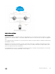
– To connect servers and access switches with VLT peer switches, you use a VLT port channel, as shown in Overview. Up to
96 port-channels are supported; up to 16 member links are supported in each port channel between the VLT domain and an
access device.
– The discovery protocol running between VLT peers automatically generates the ID number of the port channel that connects
an access device and a VLT switch. The discovery protocol uses LACP properties to identify connectivity to a common client
830
Virtual Link Trunking (VLT)