
Administrator Guide

device and automatically generates a VLT number for port channels on VLT peers that connects to the device. The discovery
protocol requires that an attached device always runs LACP over the port-channel interface.
– VLT provides a loop-free topology for port channels with endpoints on dierent chassis in the VLT domain.
– VLT uses shortest path routing so that trac destined to hosts via directly attached links on a chassis does not traverse the
chassis-interconnect link.
– VLT allows multiple active parallel paths from access switches to VLT chassis.
– VLT supports port-channel links with LACP between access switches and VLT peer switches. Dell Networking recommends
using static port channels on VLTi.
– If VLTi connectivity with a peer is lost but the VLT backup connectivity indicates that the peer is still alive, the VLT ports on
the Secondary peer are orphaned and are shut down.
* In one possible topology, a switch uses the BMP feature to receive its IP address, conguration les, and boot image from
a DHCP server that connects to the switch through the VLT domain. In the port-channel used by the switch to connect
to the VLT domain, congure the port interfaces on each VLT peer as hybrid ports before adding them to the port
channel (refer to Connecting a VLT Domain to an Attached Access Device (Switch or Server)). To congure a port in
Hybrid mode so that it can carry untagged, single-tagged, and double-tagged trac, use the portmode hybrid
command in Interface Conguration mode as described in Conguring Native VLANs.
* For example, if the DHCP server is on the ToR and VLTi (ICL) is down (due to either an unavailable peer or a link failure),
whether you congured the VLT LAG as static or LACP, when a single VLT peer is rebooted in BMP mode, it cannot
reach the DHCP server, resulting in BMP failure.
• Software features supported on VLT port-channels
– In a VLT domain, the following software features are supported on VLT port-channels: 802.1p, ingress and egress ACLs, BGP,
DHCP relay, IS-IS, OSPF, active-active PIM-SM, PIM-SSM, VRRP, Layer 3 VLANs, LLDP, ow control, port monitoring,
jumbo frames, IGMP snooping, sFlow, ingress and egress ACLs, and Layer 2 control protocols RSTP only).
NOTE: PVST+ passthrough is supported in a VLT domain. PVST+ BPDUs does not result in an interface shutdown.
PVST+ BPDUs for a nondefault VLAN is ooded out as any other L2 multicast packet. On a default VLAN, RTSP
is part of the PVST+ topology in that specic VLAN (default VLAN).
– For detailed information about how to use VRRP in a VLT domain, refer to the following VLT and VRRP Interoperability
section.
– For information about conguring IGMP Snooping in a VLT domain, refer to VLT and IGMP Snooping.
– All system management protocols are supported on VLT ports, including SNMP, RMON, AAA, ACL, DNS, FTP, SSH, Syslog,
NTP, RADIUS, SCP, TACACS+, Telnet, and LLDP.
– Enable Layer 3 VLAN connectivity VLT peers by conguring a VLAN network interface for the same VLAN on both switches.
– IGMP snooping is supported over VLT ports. The multicast forwarding state is synchronized on both VLT peer switches. The
IGMP snooping process on a VLT peer shares the learned group information with the other VLT peer over the chassis
interconnect trunk.
• Software features supported on VLT physical ports
– In a VLT domain, the following software features are supported on VLT physical ports: 802.1p, LLDP, ow control, IPv6
dynamic routing, port monitoring, and jumbo frames.
• Software features not supported with VLT
– In a VLT domain, the following software features are supported on non-VLT ports: 802.1x, DHCP snooping, FRRP, ingress and
egress QOS.
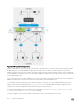
• VLT and VRRP interoperability
– In a VLT domain, VRRP interoperates with virtual link trunks that carry trac to and from access devices (refer to Overview).
The VLT peers belong to the same VRRP group and are assigned master and backup roles. Each peer actively forwards L3
trac, reducing the trac ow over the VLT interconnect.
– VRRP elects the router with the highest priority as the master in the VRRP group. To ensure VRRP operation in a VLT
domain, congure VRRP group priority on each VLT peer so that a peer is either the master or backup for all VRRP groups
congured on its interfaces. For more information, refer to Setting VRRP Group (Virtual Router) Priority.
– To verify that a VLT peer is consistently congured for either the master or backup role in all VRRP groups, use the show
vrrp
command on each peer.
– Also congure the same L3 routing (static and dynamic) on each peer so that the L3 reachability and routing tables are
identical on both VLT peers. Both the VRRP master and backup peers must be able to locally forward L3 trac in the same
way.
Virtual Link Trunking (VLT)
831