
Administrator Guide

NOTE: ARP entries learned on non-VLT, non-spanned VLANs are not synced with VLT peers.
RSTP Conguration
RSTP is supported in a VLT domain.
Before you congure VLT on peer switches, congure RSTP in the network. RSTP is required for initial loop prevention during the
VLT startup phase. You may also use RSTP for loop prevention in the network outside of the VLT port channel. For information about
how to congure RSTP, Rapid Spanning Tree Protocol (RSTP).
Run RSTP on both VLT peer switches. The primary VLT peer controls the RSTP states, such as forwarding and blocking, on both the
primary and secondary peers. Dell Networking recommends conguring the primary VLT peer as the RSTP primary root device and
conguring the secondary VLT peer as the RSTP secondary root device.
BPDUs use the MAC address of the primary VLT peer as the RSTP bridge ID in the designated bridge ID eld. The primary VLT peer
sends these BPDUs on VLT interfaces connected to access devices. The MAC address for a VLT domain is automatically selected on
the peer switches when you create the domain.
Congure both ends of the VLT interconnect trunk with identical RSTP congurations. When you enable VLT, the show
spanning-tree rstp brief command output displays VLT information.
Preventing Forwarding Loops in a VLT Domain
During the bootup of VLT peer switches, a forwarding loop may occur until the VLT congurations are applied on each switch and
the primary/secondary roles are determined.
To prevent the interfaces in the VLT interconnect trunk and RSTP-enabled VLT ports from entering a Forwarding state and creating
a trac loop in a VLT domain, take the following steps.
1. Congure RSTP in the core network and on each peer switch as described in Rapid Spanning Tree Protocol (RSTP).
Disabling RSTP on one VLT peer may result in a VLT domain failure.
2. Enable RSTP on each peer switch.
PROTOCOL SPANNING TREE RSTP mode
no disable
3. Congure each peer switch with a unique bridge priority.
PROTOCOL SPANNING TREE RSTP mode
bridge-priority
Sample RSTP Conguration
The following is a sample of an RSTP conguration.
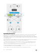
Using the example shown in the Protocol Overview section as a sample VLT topology, the primary VLT switch sends BPDUs to an
access device (switch or server) with its own RSTP bridge ID. BPDUs generated by an RSTP-enabled access device are only
processed by the primary VLT switch. The secondary VLT switch tunnels the BPDUs that it receives to the primary VLT switch over
the VLT interconnect. Only the primary VLT switch determines the RSTP roles and states on VLT ports and ensures that the VLT
interconnect link is never blocked.
In the case of a primary VLT switch failure, the secondary switch starts sending BPDUs with its own bridge ID and inherits all the
port states from the last synchronization with the primary switch. An access device never detects the change in primary/secondary
roles and does not see it as a topology change.
The following examples show the RSTP conguration that you must perform on each peer switch to prevent forwarding loops.
Virtual Link Trunking (VLT)
837