
Installation Manual


Installing S25N and S25V Systems 29
Supplying Power
Supply power to the units in a stack only after they are mounted and the stack ports are connected. There is
no on/off switch, and the stack members partly determine the stack management unit from the order in
which they come on-line (see below).
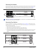
S25N
The S25N has two AC receptacles in the rear of the unit (see Figure 3 on page 10). The system can use
either power source independently, or act in load-sharing mode.
Connect the supplied AC power cord first to either receptacle (on the right as you face the rear of the system)
and then to the power source (see AC Power Requirements on page 50). Ensure that the cord is secure. If you
connect both AC power supplies, ideally you would connect them to separate circuits.
S25V
The S25V has both an AC (3-prong plug receptacle) and a DC (-48V terminal-type) connection on the
back of the unit (see Figure 2 on page 10). Each power source can be used independently or in load-sharing
combination. In other words, you have three options for providing power to the switch — AC only, DC
only, or using both AC and DC sources.
In addition, Force10 provides, as an option, an external 470W DC Redundant Power Supply Unit (PSU),
which can be connected in either load-sharing mode or current-sharing mode. For details, see Chapter 4,
Installing Backup Power, on page 31.
To use AC only, connect the supplied AC power cord first to the switch (receptacle on the right as you face
the rear of the unit) and then to the power source (see AC Power Requirements on page 50). Connect the
plug to the AC receptacle at the right rear of the switch, making sure that the power cord is secure.
For DC power, you must provide your own cables to connect to the power source. Cables must be sized for
11.5 A service at no more than -48 VDC input (per NEC in the United States; internationally; follow local
safety codes.). Before you make the cable connections, apply a coat of antioxidant paste to unplated metal
contact surfaces. File unplated connectors, braided straps, and bus bars to a shiny finish.
1 Make sure that the remote power source (the circuit breaker panel) is in the OFF position.
2. Remove the safety cover from the DC terminal block.
3. Connect the grounding cable to the FG terminal first, then connect the opposite end to the appropriate
grounding point at your site to ensure an adequate unit ground.
4. Connect the -48 V and -48 V RTN (Return) cables to the switch terminals and then to the remote
power sources. For the Current Sharing terminal, see
Chapter 4, Installing Backup Power, on page 31.
5. Replace the safety covers on the DC terminal block.
Danger: To prevent electrical shock, make sure the switch is grounded properly. If you do not ground
your equipment correctly, excessive emissions can result. Use a qualified electrician to ensure that the
power cables meet your local electrical requirements. See other relevant cautions in Information Symbols
and Warnings on page 7.