Dell™ OptiPlex™ FX160/160 Service Manual Working on Your Computer System Setup Selective USB Reinstalling Software Troubleshooting Computer Stand Covers Hard Drive Assembly (Optional) NVRAM Module Wireless Card I/O Board Power Supply Processor Heatsink Assembly Memory Coin-Cell Battery Cable Guide Antenna System Board Assembly Getting Help Finding Information Model DC01T Notes, Notices, and Cautions NOTE: A NOTE indicates important information that helps you make better use of your computer.
Back to Contents Page About Your Computer Dell™ OptiPlex™ FX160 Service Manual Front View Back View Front View 1 power button 2 side cover 3 USB 2.
NOTE: See Selective USB for information about using selective USB ports.
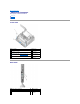
Back to Contents Page Antenna Dell™ OptiPlex™ FX160/160 Service Manual Removing the Antenna Replacing the Antenna Removing the Antenna 1. Perform the procedure in Before Working on Your Computer. 2. Remove the hard drive bracket assembly, if installed (see Removing the Hard Drive Bracket Assembly). 3. Remove the WLAN card (see Removing the Wireless Card). 4. Remove the antenna cable from under the metal tab on the back panel.
1 antenna holder 2 bushing tabs 3 wire mesh 6. Replace the WLAN card (see Replacing the Wireless Card). 7. Route the antenna cable under the tab on the back of the chassis so that the wire mesh surrounding the cable is under the tab. 8. Replace the hard drive bracket assembly if it was removed (see Replacing the Hard Drive Bracket Assembly). 9. Perform the procedure in After Working on Your Computer.
Back to Contents Page Working on Your Computer Dell™ OptiPlex™ FX160/160 Service Manual Recommended Tools Before Working on Your Computer After Working on Your Computer This document provides procedures for removing and installing the components in your computer. Unless otherwise noted, each procedure assumes that: l You have performed the steps in this section. l You have read the safety information that shipped with your computer.
4. Disconnect any network cables from the computer. 5. If applicable, remove the computer stand (see Removing the Computer Stand). WARNING: To guard against electrical shock, always unplug your computer from the electrical outlet before removing the computer cover. 6. Remove the computer cover (see Removing the Computer Cover). After Working on Your Computer After you complete any replacement procedures, ensure you connect any external devices, cards, cables, etc.
Back to Contents Page Cable Guide Dell™ OptiPlex™ FX160/160 Service Manual Removing the Cable Guide Replacing the Cable Guide Removing the Cable Guide 1. Remove the screw that secures the cable guide to the system board. 2. Lift the guide out of the computer. Replacing the Cable Guide 1. Align the cable guide screw hole with the hole on the system board. 2. Secure the cable guide to the system board with the screw. .
Back to Contents Page Coin-Cell Battery Dell™ OptiPlex™ FX160/160 Service Manual Removing the Coin-Cell Battery Replacing the Coin-Cell Battery One of two types of coin-cell battery sockets is provided with the your computer. One type has retaining clips that wrap along the sides of the battery to hold it in the socket. The other type has a single retaining hook that holds the battery in place.
Back to Contents Page Covers Dell™ OptiPlex™ FX160/160 Service Manual Removing the Computer Cover Replacing the Computer Cover Removing the Side Cover Replacing the Side Cover Removing the Computer Cover WARNING: Always unplug your computer from the electrical outlet before removing the computer cover. WARNING: Some components become very hot during normal operation. Allow system components to cool before touching them. 1. Disconnect the security cable from the computer (if present).
5. Reattach the security cable to your computer, if necessary. Removing the Side Cover 1. 1 Lift the back edge of the side cover away from the chassis, then slip the hooks under the front edge of the side cover out of the slots on the side of the chassis. side cover 2 side cover hooks slots Replacing the Side Cover 1. 2.
1 peg (2) 2 peg retainer (2) 3 side cover hooks (2) 4 side cover hook slots(2) Back to Contents Page
Back to Contents Page Finding Information Dell™ OptiPlex™ FX160/160 Service Manual NOTE: Some features or media may be optional and may not ship with your computer. Some features or media may not be available in certain countries. NOTE: Additional information may ship with your computer. Document/Media/Label Contents Service Tag Express Service Code l The Service Tag/Express Service Code is located on your computer and on the BIOS Setup Utility screen.
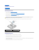
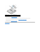
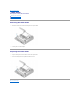
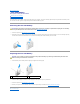
Back to Contents Page Hard Drive Assembly (Optional) Dell™ OptiPlex™ FX160/160 Service Manual Removing the Hard Drive Bracket Assembly Replacing the Hard Drive Bracket Assembly Removing the Hard Drive Replacing the Hard Drive Removing the Hard Drive Fan Replacing the Hard Drive Fan Removing the Hard Drive Bracket Assembly 1. Loosen the two captive bracket screws on system board and remove the screw that secures the bracket to the back panel.
1 SATA hard drive power cable 2 fan cable 3 cable retaining clip 4 SATA data cable 5 bracket screw 6 captive screws (2) Removing the Hard Drive 1. Perform the procedure in Before Working on Your Computer. 2. Remove the hard drive bracket assembly (see Removing the Hard Drive Bracket Assembly). 3. Disconnect the SATA data/power cable from the hard drive. 4. Remove the four screws that secure the hard drive to the hard drive bracket assembly.
NOTE: Ensure that the SATA power cable is routed under the hard drive bracket cable retaining clip. 5. Replace the hard drive bracket assembly (see Replacing the Hard Drive Bracket Assembly). 6. Perform the procedure in After Working on Your Computer. Removing the Hard Drive Fan 1. Perform the procedure in Before Working on Your Computer. 1. Remove the hard drive bracket assembly (see Removing the Hard Drive Bracket Assembly). 2.
Back to Contents Page Processor Heatsink Assembly Dell™ OptiPlex™ FX160/160 Service Manual Removing the Processor Heatsink Assembly Replacing the Processor Heatsink Assembly Removing the Processor Heatsink Assembly 1. Perform the procedure in Before Working on Your Computer. 2. Remove the hard drive bracket assembly, if installed (see Removing the Hard Drive Bracket Assembly). 3. Loosen the two captive screws that secure the processor heatsink assembly to the system board.
3. Tighten the two captive screws to secure the processor heatsink assembly to the system board. 4. Replace the hard drive bracket assembly if it was removed (see Replacing the Hard Drive Bracket Assembly). 5. Perform the procedure in After Working on Your Computer.
Back to Contents Page Getting Help Dell™ OptiPlex™ FX160/160 Service Manual Obtaining Assistance Problems With Your Order Product Information Returning Items for Warranty Repair or Credit Before You Call Contacting Dell Obtaining Assistance WARNING: Before working inside your computer, read the safety information that shipped with your computer. For additional safety best practices information, see the Regulatory Compliance Homepage at www.dell.com/regulatory_compliance.
www.dell.ca (Canada only) You can access Dell Support through the following websites and e-mail addresses: l Dell Support websites: support.dell.com support.jp.dell.com (Japan only) support.euro.dell.com (Europe only) l Dell Support e-mail addresses: mobile_support@us.dell.com support@us.dell.com la-techsupport@dell.com (Latin America and Caribbean countries only) apsupport@dell.com (Asian/Pacific countries only) l Dell Marketing and Sales e-mail addresses: apmarketing@dell.
4. Pack the equipment to be returned in the original (or equivalent) packing materials. You are responsible for paying shipping expenses. You are also responsible for insuring any product returned, and you assume the risk of loss during shipment to Dell. Collect On Delivery (C.O.D.) packages are not accepted. Returns that are missing any of the preceding requirements will be refused at Dell's receiving dock and returned to you. Before You Call NOTE: Have your Express Service Code ready when you call.
Back to Contents Page I/O Board Dell™ OptiPlex™ FX160/160 Service Manual Removing the I/O Board Replacing the I/O Board Removing the I/O Board 1. Perform the procedure in Before Working on Your Computer. 2. Remove the two screws that secure the I/O board to the chassis. 1 screws (2) 2 cable guide 3. Carefully lift the I/O board out of the computer, ensuring the three cables are clear of the cable guide. 4.
1 cable guide metal tab 4. metal clip Perform the procedure in After Working on Your Computer.
Back to Contents Page Memory Dell™ OptiPlex™ FX160/160 Service Manual Removing a Memory Module Replacing a Memory Module Your computer supports one or two memory modules. NOTE: Your computer supports non-ECC, 667 MHz or 800 MHz, DDR2 SDRAM only. It supports memory module sizes of 512 MB (for embedded Linux operating systems only), 1 GB, and 2 GB. When 800 MHz memory is installed, your computer operates at 667 MHz. See support.dell.com for more information. Removing a Memory Module 1.
connector 3 DIMM_2 memory connector 3. Perform the procedure in After Working on Your Computer.
Back to Contents Page NVRAM Module Dell™ OptiPlex™ FX160/160 Service Manual Removing the NVRAM Module Replacing the NVRAM Module Removing the NVRAM Module 1. Perform the procedure in Before Working on Your Computer. 2. Remove the hard drive bracket assembly, if installed (see Removing the Hard Drive Bracket Assembly). 3. Remove the screw that secures the NVRAM module to the system board with a Phillips #1 screwdriver. 1 NVRAM module 4.
Back to Contents Page
Back to Contents Page Power Supply Dell™ OptiPlex™ FX160/160 Service Manual Removing the Power Supply Replacing the Power Supply Removing the Power Supply 1. Perform the procedure in Before Working on Your Computer. WARNING: The power supply can become very hot during normal operation. Allow the power supply to cool before touching it. 2. Disconnect the 12V power supply connector from the system board (see System Board Connectors).
2. Secure the power supply with a back panel screw and the chassis screw. 3. Connect the 12V power supply connector to the system board (see System Board Connectors). 4. Perform the procedure in After Working on Your Computer.
Back to Contents Page Reinstalling Software Dell™ OptiPlex™ FX160/160 Service Manual Drivers Restoring Your Operating System User Accounts and Passwords CAUTION: To install or update software on your computer, you must be logged in with administrative privileges. Use extreme care when operating your computer with administrative privileges to prevent damage to the system software. NOTE: Microsoft® Windows® XP Embedded is available on the OptiPlex FX160 system only.
b. If the Control Panel window appears in Category View (Pick a category), switch to Classic View (icon view). c. Double-click the System icon. d. In the System Properties window, click the Hardware tab, and then click Device Manager. 2. Right-click the device for which the new driver was installed and click Properties. 3. Click the Drivers tab® Roll Back Driver.
8. Click Finish and restart your computer. Restoring Your Operating System Depending on your system configuration, you can restore your operating system in the following ways: l l l For systems with the operating system installed on NVRAM module, the operating system can be re-imaged. Microsoft® Windows System Restore (available only on computers that have hard drives and are running Windows Vista) returns your computer to an earlier operating state without affecting data files.
Restoring Your Operating System Using the Operation System Media Before you Begin If you are considering reinstalling the Windows operating system to correct a problem with a newly installed driver, first try using Windows Device Driver Rollback. See Returning to a Previous Device Driver Version. If Device Driver Rollback does not resolve the problem, then use Microsoft Windows System Restore to return your operating system to the operating state it was in before you installed the new device driver.
3. Click Administrative Tools ® UserManager. 4. In the left pane, click either Users or Groups, then double-click the name whose attributes you want to change. Windows XP 1. Click Start® Control Panel. 2. If the Control Panel window appears in Category View (Pick a category), switch to Classic View (icon view). 3. Click User Accounts. 4. Click the User Name whose password or privileges you want to change, and follow the on-screen instructions. Windows Vista 1.
Back to Contents Page Computer Stand Dell™ OptiPlex™ FX160/160 Service Manual Removing the Computer Stand Replacing the Computer Stand Removing the Computer Stand 1. Gently press down on the metal tab at the back of the computer. 2. Slide the stand toward the back of the computer approximately 1/4 of an inch. 3. Remove the stand from the computer. Replacing the Computer Stand 1. 2. Grasp the computer by the top of the chassis.
Back to Contents Page System Board Assembly Dell™ OptiPlex™ FX160/160 Service Manual System Board Connectors Removing the System Board Assembly Replacing the System Board System Board Connectors 1 memory connector (DIMM_1) 2 memory connector (DIMM_2) 3 battery (BATTERY) 4 audio connector (AUDIOF1) 5 USB connector (USBF1) 6 setup jumper (SETUP_LOCK) 7 front panel connector (FRONTPANEL) 8 SATA data cable connector (SATA_1) 9 NVRAM module connector (SATA_0) 10 clear CMOS jumper (
8. Disconnect the I/O board cables from the system board. 9. Disconnect the 12V power supply connector from the system board (see System Board Connectors). 10. Remove the cable guide (see Removing the Cable Guide). 11. Remove the two screws on the back corners of the system board that secure it to the chassis.
10. Replace the NVRAM module if it was removed (see Replacing the NVRAM Module). 11. Replace the processor heatsink assembly (see Replacing the Processor Heatsink Assembly). 12. Replace the hard drive bracket assembly if it was removed (see Replacing the Hard Drive Bracket Assembly). 13. Perform the procedure in After Working on Your Computer. 14. Restart your computer and enter the BIOS setup to configure parameter settings as needed (see Entering the BIOS Setup Utility).
Back to Contents Page System Setup Dell™ OptiPlex™ FX160/160 Service Manual Overview Boot Sequence Entering the BIOS Setup Utility Clearing Forgotten Passwords BIOS Setup Utility Screens Clearing CMOS Settings BIOS Setup Utility Options Flashing the BIOS Setup Lock Overview Use the BIOS Setup Utility to: l To change the system configuration information after you add, change, or remove any hardware in your computer l Enable or disable system board devices l Enable or d
Info clock speed, and L2 cache. Memory Info Indicates amount of installed memory, memory speed, channel mode, and type of memory installed. Boot Sequence Specifies the boot sequence for device types. Drives Displays the SATA drives in the system (SATA -0, NVRAM; SATA-1, hard disk drive), drive operation and SMART reporting state. Onboard Devices Displays the enable status of system board components.
l Network Drive — The computer may receive its operating system from a network drive, such as an ImageServer. Changing Boot Sequence for Future Boots When establishing the boot sequence, first establish the boot order of devices within device type groups, then select the boot order of device types. 1. Enter the BIOS Setup Utility (see Entering the BIOS Setup Utility). 2. Use the left- and right-arrow keys to navigate to the System screen. 3.
5. Shut down your computer. 6. Perform the procedure in Before Working on Your Computer. 7. Replace the jumper on the password jumper (PSWD) pins. 8. Perform the procedure in After Working on Your Computer. NOTE: This procedure enables the password feature. When you enter the BIOS Setup Utility, both system and administrator password options appear as Not Set—meaning that the password feature is enabled but no password is assigned. 9. 10.
7. Click Close if the Download Complete window appears. The file icon appears on your desktop and is titled the same as the downloaded BIOS update file. 8. Double-click the file icon on the desktop and follow the instructions on the screen.
Back to Contents Page Dell™ OptiPlex™ FX160/160 Service Manual NOTE: A NOTE indicates important information that helps you make better use of your computer. CAUTION: A CAUTION indicates potential damage to hardware or loss of data if instructions are not followed. WARNING: A WARNING indicates a potential for property damage, personal injury, or death. If you purchased a Dell™ n Series computer, any references in this document to Microsoft® Windows® operating systems are not applicable.
Back to Contents Page Troubleshooting Dell™ OptiPlex™ FX160/160 Service Manual Tools Dell Diagnostics Solving Problems Dell Technical Update Service WARNING: Before working inside your computer, read the safety information that shipped with your computer. For additional safety best practices information, see the Regulatory Compliance Homepage at www.dell.com/regulatory_compliance. WARNING: Always unplug your computer from the electrical outlet before opening the computer cover.
A possible BIOS failure has occurred; the computer is in the recovery mode. l l Clear CMOS (see Clearing CMOS Settings) Re-flash the BIOS or install a BIOS update (see Flashing the BIOS) and restart the computer. If the problem persists, contact Dell (see Contacting Dell). A possible processor failure has occurred. l Contact Dell (see Contacting Dell). Memory modules are detected, but a memory failure has occurred.
l normally, continue to install additional memory modules (one at a time) until you have identified a faulty module or reinstalled all modules without error. If available, install working memory of the same type into your computer (see Memory). If the problem persists, contact Dell (see Contacting Dell). l If the problem persists, contact Dell (see Contacting Dell). l Ensure that no special requirements for memory module/connector placement exist (see Memory).
Not a boot diskette — Insert a bootable floppy disk and restart your computer. NOTICE – Hard Drive SELF MONITORING SYSTEM has reported that a parameter has exceeded its normal operating range. Dell recommends that you back up your data regularly. A parameter out of range may or may not indicate a potential hard drive problem. — S.M.A.R.T error, possible HDD failure. This feature can be enabled or disabled in BIOS setup.
Before running the Dell Diagnostics, enter the BIOS Setup Utility to review your computer's configuration information, and ensure that the device you want to test is displayed in the BIOS Setup Utility and is active. NOTE: If your computer does not display a screen image, contact Dell (see Contacting Dell). 1. Ensure that the computer is connected to an electrical outlet that is known to be working properly. 2. Turn on (or restart) your computer. 3.
NOTE: Using the one-time boot menu changes the boot sequence for the current boot only. Upon restart, the computer boots according to the boot sequence specified in the BIOS Setup Utility. 6. Press any key to confirm that you want to start from the CD/DVD. 7. Type 1 to Run the 32 Bit Dell Diagnostics. 8. At the Dell Diagnostics Main Menu, type 1 to select Dell 32-bit Diagnostics for Resource CD (graphical user interface). 9. Press to select Test System and then press .
Tab Function Results Displays the results of the test and any error conditions encountered. Errors Displays error conditions encountered, error codes, and the problem description. Help Describes the test and any requirements for running the test. Configuration Displays the hardware configuration for the selected device.
Check cable connections — Check the HDD cable connections (see Hard Drive Assembly (Optional)), and NVRAM module (see NVRAM Module) to ensure that they are seated properly. Clean the drive or disc — use commercially available disc cleaning materials to ensure the disc and optical drive are clean. Run the Hardware Troubleshooter — See Hardware Troubleshooter. Run the Dell Diagnostics — See Dell Diagnostics.
4. Click Scan for and attempt recovery of bad sectors and then click Start. 5. If a disk problem is found, follow the screen instructions to fix the problem. Windows Vista: 1. Click Start 2. Right-click Local Disk C:. and click Computer. 3. Click Properties® Tools® Check Now. The User Account Control window may appear. If you are an administrator on the computer, click Continue; otherwise, contact your administrator to continue the desired action. 4.
1. Click Start ® Control Panel® Programs® Programs and Features. 2. Select the program you want to remove. 3. Click Uninstall. 4. See the program documentation for installation instructions. drive letter :\ is not accessible. The device is not ready — The drive cannot read the disk. Insert a disk into the drive and try again. Insert bootable media — Insert a bootable floppy disk, CD, or DVD.
Turn the computer off — If you are unable to get a response by pressing a key on your keyboard or moving your mouse, press and hold the power button for at least 8 to 10 seconds (until the computer turns off), and then restart your computer. A program stops responding End the program — 1. Press simultaneously to access the Task Manager. 2. Click the Applications tab. 3. Click to select the program that is no longer responding. 4. Click End Task.
Other software problems Check the software documentation or contact the software manufacturer for troubleshooting information — l Ensure that the program is compatible with the operating system installed on your computer. l Ensure that your computer meets the minimum hardware requirements needed to run the software. See the software documentation for information. l Ensure that the program is installed and configured properly. l Verify that the device drivers do not conflict with the program.
Test the mouse — Connect a properly working mouse to the computer, then try using the mouse. Check the mouse settings — Windows XP and Windows XP Embedded: 1. Click Start® Control Panel. 2. If the Control Panel window appears in Category View (Pick a category), switch to Classic View (icon view). 3. Click Mouse. 4. Adjust the settings as needed. Windows Vista: 1. Click Start 2. Adjust the settings as needed. ® Control Panel® Hardware and Sound® Mouse.
If the power light is blue and the computer is not responding — See Diagnostic Lights. If the power light is blinking blue — The computer is in standby mode. Press a key on the keyboard, move the mouse, or press the power button to resume normal operation. If the power light is off — The computer is either turned off or is not receiving power. l Reseat the power cable in the power connector on the back of the computer and the electrical outlet.
1. Click Start ® Control Panel® Hardware and Sound® Printer. 2. If the printer is listed, right-click the printer icon. 3. Click Properties® Ports. 4. Adjust the settings, as needed. Reinstall the printer driver — See the printer documentation for information on reinstalling the printer driver. Scanner Problems WARNING: Before working inside your computer, read the safety information that shipped with your computer.
WARNING: Before working inside your computer, read the safety information that shipped with your computer. For additional safety best practices information, see the Regulatory Compliance Homepage at www.dell.com/regulatory_compliance. No sound from speakers NOTE: The volume control in MP3 and other media players may override the Windows volume setting. Always check to ensure that the volume on the media player(s) has not been turned down or off.
Test the mouse controller — To test the mouse controller (which affects pointer movement) and the operation of the mouse buttons, run the Mouse test in the Pointing Devices test group in the Dell Diagnostics (see Dell Diagnostics). Reinstall the mouse driver — See Reinstalling Drivers and Utilities. Video and Monitor Problems WARNING: Before working inside your computer, read the safety information that shipped with your computer.
2. Adjust Resolution and Colors settings, as needed. Dell Technical Update Service The Dell Technical Update service provides proactive e-mail notification of software and hardware updates for your computer. The service is free and can be customized for content, format, and how frequently you receive notifications. To enroll for the Dell Technical Update service, go to support.dell.com/technicalupdate.
Back to Contents Page Selective USB Dell™ OptiPlex™ FX160/160 Service Manual Overview Enabling Selective USB Overview Selective USB allows administrators to restrict two USB ports to support only a keyboard and a mouse and disable all other USB ports. When using a selective USB port, you must connect the keyboard and mouse to the specific USB ports before booting the computer. A keyboard (without a USB hub) is required for the system to boot.
Back to Contents Page Wireless Card Dell™ OptiPlex™ FX160/160 Service Manual Removing the Wireless Card Replacing the Wireless Card Removing the Wireless Card 1. Perform the procedure in Before Working on Your Computer. 2. Remove the hard drive bracket assembly, if installed (Removing the Hard Drive Bracket Assembly). 3. Pull back the metal tab until the wireless card pops up at a 45-degree angle. 1 wireless card 2 metal tab 4.
4. Route the antenna cable to ensure that the metal mesh sleeve on the cable is secured by the tab on the back panel. 5. Replace the hard drive bracket assembly if it was removed (see Replacing the Hard Drive Bracket Assembly). 6. Perform the procedure in After Working on Your Computer.