Dell EMC PowerEdge T350 Installation and Service Manual Regulatory Model: E78S series Regulatory Type: E78S001 October 2021 Rev.
Notes, cautions, and warnings NOTE: A NOTE indicates important information that helps you make better use of your product. CAUTION: A CAUTION indicates either potential damage to hardware or loss of data and tells you how to avoid the problem. WARNING: A WARNING indicates a potential for property damage, personal injury, or death. © 2021 Dell Inc. or its subsidiaries. All rights reserved. Dell, EMC, and other trademarks are trademarks of Dell Inc. or its subsidiaries.
Contents Chapter 1: About this document.................................................................................................... 7 Chapter 2: PowerEdge T350 system overview............................................................................... 8 Front view of the system.................................................................................................................................................. 9 Rear view of the system...................................................
Drives................................................................................................................................................................................... 38 Removing a drive blank.............................................................................................................................................. 38 Installing a drive blank...................................................................................................................................
Installing the MicroSD card.......................................................................................................................................84 Optional internal USB card............................................................................................................................................. 85 Removing the internal USB card.............................................................................................................................
Using system diagnostics.............................................................................................................................................. 125 Dell Embedded System Diagnostics...................................................................................................................... 125 Chapter 9: Getting help............................................................................................................. 126 Recycling or End-of-Life service information.....
1 About this document This document provides an overview about the system, information about installing and replacing components, diagnostic tools, and guidelines to be followed while installing certain components.
2 PowerEdge T350 system overview The PowerEdge T350 system is a 4.5U tower server that supports: ● One Intel Xeon E-2300 Series processor or Intel Pentium processor ● Four DDR4 DIMM slots ● Two redundant or one cabled AC power supply units ● Up to eight 3.5-inch SAS/SATA hot swap drives NOTE: All instances of SAS, SATA drives are seen as drives in this document, unless specified otherwise. NOTE: For more information, see the Dell EMC PowerEdge T350 Technical Specifications on the product documentation page.
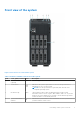
Front view of the system Figure 1. Front view of 8 x 3.5-inch drive system Table 1. Features available on the front of the system Item Ports, panels, and slots Icon Description 1 BOSS S2 module (optional) This slot supports BOSS S2 module. 2 Power button 3 Information tag 4 System health and ID indicator N/A Indicates if the system is powered on or off. Press the power button to manually power on or off the system.
Table 1. Features available on the front of the system (continued) Item Ports, panels, and slots Icon Description 5 USB 3.0 port The USB ports are 9-pin, 3.0-compliant. These ports enable you to connect USB devices to the system. 6 iDRAC Direct port (Micro-AB USB) The iDRAC Direct port is micro USB 2.0-compliant. This port enables you to access the iDRAC Direct features. For more information, see the Integrated Dell Remote Access Controller User's Guide at www.dell.com/ poweredgemanuals.
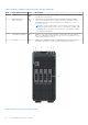
Table 2. Features available on the front of the system Item Ports, panels, and slots Icon Description 1 BOSS S2 module (optional) This slot supports BOSS S2 module. 2 Power button 3 Information tag 4 System health and ID indicator Indicates the system health. For more information, see the System health and system ID indicator codes section. 5 USB 3.0 port The USB ports are 9-pin, 3.0-compliant. These ports enable you to connect USB devices to the system.
Rear view of the system Figure 3. Rear view of the system with redundant PSU Table 3. Rear view of the system Item Ports, panels, or slots 1 Power supply unit (PSU 1) PSU1 is the primary PSU of the system. For more information about the PSU configurations, see the Dell EMC PowerEdge T350 Technical Specifications on product documentation page. 2 Power supply unit (PSU 2) This is a secondary PSU or redundant PSU.
Table 3. Rear view of the system (continued) Item Ports, panels, or slots 5 System identification button Icon Description Press the system ID button: ● To locate a particular system within a rack. ● To turn the system ID on or off. To reset iDRAC, press and hold the button for 16 seconds. NOTE: ● To reset iDRAC using system ID, ensure that the system ID button is enabled in the iDRAC setup.
Figure 4. Rear view of the system with cable PSU Table 4. Rear view of the system Item Ports, panels, or slots Icon Description 1 Cabled power supply unit 2 PCIe expansion card slots (4) 3 USB 2.0 port (4) The USB ports are 4-pin, 2.0-compliant. These ports enable you to connect USB devices to the system. 4 System identification button Press the system ID button: ● To locate a particular system within a rack. ● To turn the system ID on or off.
Table 4. Rear view of the system (continued) Item Ports, panels, or slots Icon Description ● If the system stops responding during POST, press and hold the system ID button (for more than five seconds) to enter the BIOS progress mode. 5 NIC port (1) The NIC ports are embedded on the LOM card that is connected to the system board. 6 USB 3.0 port (1) The USB ports are 9-pin, 3.0-compliant. These ports enable you to connect USB devices to the system. 7 USB 2.0 port (1) The USB ports are 4-pin, 2.
Inside the system Figure 5. Inside the system with redundant PSU 1. 3. 5. 7. 9. 16 PIB (Power Interface Board) PCIe expansion card Intrusion switch Memory module sockets Backplane PowerEdge T350 system overview 2. 4. 6. 8.
Figure 6. Inside the system with cabled PSU 1. 3. 5. 7. 9. Cabled PSU System board Cooling fan Heat sink Backplane 2. 4. 6. 8. PCIe expansion card Intrusion switch Memory module sockets Internal Dual SD module (IDSDM)/USB card (optional) Locating the Express Service Code and Service Tag The unique Express Service Code and Service Tag are used to identify the system.
2. 3. 4. 5. Information tag (back view) OpenManage Mobile (OMM) label iDRAC MAC address and iDRAC secure password label Service Tag, Express Service Code, QRL label The Mini Enterprise Service Tag (MEST) label is located on the rear of the system that includes the Service Tag (ST), Express Service Code (Exp Svc Code), and Manufacture Date (Mfg. Date). The Exp Svc Code is used by Dell EMC to route support calls to the appropriate personnel.
Figure 9. Electrical overview and icon legend Figure 10.
Figure 11.
3 Initial system setup and configuration This section describes the tasks for initial setup and configuration of the Dell EMC system. The section also provides general steps to set up the system and the reference guides for detailed information. Topics: • • • Setting up the system iDRAC configuration Resources to install operating system Setting up the system Perform the following steps to set up the system: Steps 1. Unpack the system. 2.
Table 5. Interfaces to set up iDRAC IP address (continued) Interface Documentation links see KB article https://www.dell.com/support/article/ sln308699. OpenManage Deployment Toolkit Dell EMC OpenManage Deployment Toolkit User's Guide available at https://www.dell.com/openmanagemanuals > Open Manage Deployment Toolkit. iDRAC Direct Integrated Dell Remote Access Controller User's Guide at https://www.dell.
Resources to install operating system If the system is shipped without an operating system, you can install a supported operating system by using one of the resources provided in the table below. For information about how to install the operating system, see the documentation links provided in the table below. Table 6. Resources to install the operating system Resource Documentation links iDRAC Integrated Dell Remote Access Controller User's Guide at https://www.dell.
Table 8. Options to download and install OS drivers (continued) Option Documentation iDRAC virtual media Integrated Dell Remote Access Controller User's Guide at https://www.dell.com/idracmanuals or for system specific Integrated Dell Remote Access Controller User's Guide, go to https://www.dell.com/poweredgemanuals > Product Support page of your system > Documentation . NOTE: To determine the most recent iDRAC release for your platform and for latest documentation version, see https://www.dell.
4 Minimum to POST and system management configuration validation This section describes the minimum to POST system requirement and system management configuration validation of the Dell EMC system.
Table 9. Configuration validation error (continued) Error Description Possible cause and recommendations Example Comm Error A configuration element is not responding to iDRAC using the management interface while running an inventory check. System management sideband communication Comm Error: Backplane 2 Unplug AC Power, reseat the element and replace the element if the problem persists.
5 Installing and removing system components Topics: • • • • • • • • • • • • • • • • • • • • • • • • • • • • Safety instructions Before working inside your system After working inside your system Recommended tools Optional front bezel System feet System cover Air shroud Intrusion switch module Drives Optional optical drive Drive backplane Cooling fans Cable routing System memory Processor and heat sink module Expansion cards Optional BOSS S2 module Optional IDSDM module MicroSD card Optional internal USB ca
NOTE: While replacing faulty storage controller, FC, or NIC card with the same type of card, after you power on the system; the new card automatically updates to the same firmware and configuration of the faulty one. For more information about the Part replacement configuration, see the Lifecycle Controller User's Guide at https://www.dell.com/idracmanuals. CAUTION: Do not install GPUs, network cards, or other PCIe devices on your system that are not validated and tested by Dell.
NOTE: The bezel key is part of the LCD bezel package. Steps 1. Unlock the bezel. 2. Holding the edges at the top, tilt the bezel to release from the system. 3. Unhook the bezel tabs from the slots at the bottom, and lift the bezel. Figure 12. Removing the front bezel Next steps Replace the front bezel. Installing the front bezel Prerequisites 1. Follow the safety guidelines listed in Safety instructions. 2. Locate and remove the bezel key. NOTE: The bezel key is part of the bezel package. Steps 1.
Figure 13. Installing the front bezel System feet Removing the system feet Prerequisites 1. Follow the safety guidelines listed in Safety instructions. 2. Place the system on its side on a flat, stable surface. 3. Rotate the system feet inward. Steps 1. Using the Phillips 2 screwdriver, remove the screw that secures the foot to the base of the system. 2. Repeat the preceding step to remove the remaining system feet.
Figure 14. Removing the system feet Next steps 1. Replace the system feet. Installing the system feet Prerequisites CAUTION: Install the feet on a stand-alone tower system to provide stability to the system. An unstable system might tip over and cause injury to the user or damage to the system. 1. Follow the safety guidelines listed in Safety instructions. 2. Place the system on its side on a flat, stable surface. Steps 1.
Figure 15. Installing the system feet Next steps 1. Place the system upright on a flat, stable surface, and rotate the system feet outward. 2. Follow the procedure listed in After working inside your system. System cover Removing the system cover Prerequisites 1. 2. 3. 4. 5. Follow the safety guidelines listed in Safety instructions. Remove the front bezel. Power off the system and any attached peripherals. Disconnect the system from the electrical outlet and peripherals.
Figure 16. Removing the system cover Next steps Replace the system cover. Installing the system cover Prerequisites 1. 2. 3. 4. 5. Follow the safety guidelines listed in Safety instructions. Remove the front bezel. Power off the system and any attached peripherals. Disconnect the system from the electrical outlet and peripherals. Ensure that all internal cables are connected and placed out of the way and no tools or extra parts are left inside the system. Steps 1.
Figure 17. Installing the system cover Next steps 1. Place the system upright on its feet on a flat, stable surface. 2. Install the front bezel. 3. Reconnect the peripherals, and connect the system to the electrical outlet and then power on the system.
Air shroud Removing the air shroud Prerequisites CAUTION: Never operate your system with the air shroud removed. The system may get overheated quickly, resulting in shutdown of the system and loss of data. 1. Follow the safety guidelines listed in Safety instructions. 2. Follow the procedure listed in Before working inside your system. Steps Holding the touch points, lift the air shroud out of the system. Figure 18. Removing the air shroud Next steps 1. Replace the air shroud.
Steps 1. Align the tabs on the air shroud with the slots on the system. 2. Lower the air shroud into the system until it is firmly seated. Figure 19. Installing the air shroud Next steps Follow the procedure listed in After working inside your system Intrusion switch module This is a service technician replaceable part only. Removing the intrusion switch module Prerequisites 1. 2. 3. 4. Follow the safety guidelines listed in Safety instructions.
Figure 20. Removing the intrusion switch module Next steps Replace the intrusion switch module. Installing the intrusion switch module Prerequisites 1. Follow the safety guidelines listed in Safety instructions. 2. Follow the procedure listed in Before working inside your system. Steps 1. Align and slide the intrusion switch module into the system slot until firmly seated. 2. Connect the intrusion switch cable to the connector on the system board. Figure 21.
Next steps 1. Install the air shroud. 2. Follow the procedure that is listed in After working inside your system. Drives Removing a drive blank Prerequisites 1. Follow the safety guidelines listed in Safety instructions. 2. Follow the procedure listed in Before working inside your system. 3. Remove the front bezel. CAUTION: To maintain proper system cooling, drive blanks must be installed in all empty drive slots. CAUTION: Mixing drive blanks from previous generations of PowerEdge servers is not supported.
Figure 23. Installing a drive blank Next steps 1. Replace the front bezel. 2. Follow the procedure listed in After working inside your system. Removing a drive carrier Prerequisites 1. Follow the safety guidelines listed in Safety instructions. 2. Remove the front bezel. 3. Using the management software, prepare the drive for removal. If the drive is online, the green activity or fault indicator flashes while the drive is turning off. When the drive indicators are off, the drive is ready for removal.
Figure 24. Removing a drive carrier Next steps Replace the drive or a drive blank. Installing the drive carrier Prerequisites CAUTION: Before removing or installing a drive while the system is running, see the documentation for the storage controller card to ensure that the host adapter is configured correctly to support drive removal and insertion. CAUTION: Combining SAS and SATA drives in the same RAID volume is not supported.
Figure 25. Installing a drive carrier Next steps Install the front bezel. Removing the drive from the drive carrier Prerequisites 1. Follow the safety guidelines listed in Safety instructions. 2. Remove the front bezel. 3. Remove the drive carrier. Steps 1. Using a Phillips 1 screwdriver, remove the screws from the slide rails on the drive carrier. NOTE: If the hard drive or SSD carrier has Torx screw, use Torx 6 (for 2.5-inch drive) or Torx 8 (for 3.5-inch drive) screw driver to remove the drive. 2.
Figure 26. Removing the drive from the drive carrier Next steps 1. Replace the drive into the drive carrier. Installing the drive into the drive carrier Prerequisites 1. Follow the safety guidelines listed in Safety instructions. 2. Remove the front bezel. 3. Remove the drive carrier. Steps 1. Insert the drive into the drive carrier with the connector end of the drive towards the rear of the carrier. 2. Align the screw holes on the drive with the screws holes on the drive carrier. 3.
Figure 27. Installing a drive into the drive carrier Next steps 1. Install the drive carrier. 2. Install the front bezel. Removing a 3.5-inch drive adapter from a 3.5-inch drive carrier Prerequisites 1. Follow the safety guidelines listed in Safety instructions. 2. Remove the drive carrier. Steps 1. Remove the screws from the rails on the drive carrier. NOTE: If the 3.5-inch drive has Torx screw, use Torx 6 screwdriver to remove the drive from a 3.5-inch drive adapter. 2. Lift the 3.
Figure 28. Removing a 3.5-inch drive adapter from a 3.5-inch drive carrier Next steps Replace a 3.5-inch adapter into a 3.5-inch drive carrier. Installing a 3.5-inch adapter into a 3.5-inch drive carrier Prerequisites 1. Follow the safety guidelines listed in Safety instructions. 2. Remove the drive carrier. Steps 1. Insert the 3.5 inch drive adapter into the drive carrier with the connector end of the drive toward the rear of the drive carrier. 2.
Figure 29. Installing a 3.5-inch drive adapter into the 3.5-inch drive carrier Next steps 1. Install the drive carrier. Removing a 2.5-inch drive from the 3.5-inch drive adapter Prerequisites 1. Follow the safety guidelines listed in Safety instructions 2. Remove the drive carrier. 3. Remove 3.5-inch drive adapter from the 3.5-inch drive carrier. NOTE: A 2.5-inch hot swappable drive is installed in a 3.5-inch drive adapter, which is then installed in the 3.5-inch hot swappable drive carrier. Steps 1.
Figure 30. Removing a 2.5-inch drive from the 3.5-inch drive adapter Next steps Replace a 2.5-inch drive into the 3.5-inch drive adapter. Installing a 2.5-inch drive into the 3.5-inch drive adapter Prerequisites 1. Follow the safety guidelines listed in Safety instructions. 2. Remove the drive carrier. 3. Remove 3.5-inch drive adapter from the 3.5-inch drive carrier. Steps 1. Align the screw holes on the 2.5-inch drive with the screw holes on the 3.5-inch drive adapter. 2.
Figure 31. Installing a 2.5-inch drive into the 3.5-inch drive adapter Next steps 1. Install a 3.5-inch adapter into the 3.5-inch drive carrier. 2. Install the drive carrier. Optional optical drive This is a service technician replaceable part only. Removing the optical drive blank Prerequisites 1. Follow the safety guidelines listed in Safety instructions. 2. Follow the procedure that is listed in Before working inside your system. 3. Remove the front bezel.
Figure 32. Removing the optical drive blank from the optical drive cage Next steps Replace the optical drive blank or install the optical drive. Installing the optical drive blank Prerequisites 1. Follow the safety guidelines listed in Safety instructions. 2. Follow the procedure that is listed in Before working inside your system. 3. Remove the front bezel. Steps Align and slide the optical drive blank into the optical drive slot until the release latch snaps into place.
Figure 33. Installing the optical drive blank into the optical drive cage Next steps 1. Install the front bezel. 2. Follow the procedure that is listed in After working inside your system. Removing the optical drive Prerequisites 1. 2. 3. 4. Follow the safety guidelines listed in Safety instructions. Follow the procedure that is listed in Before working inside your system. Remove the front bezel. Disconnect the power and data cables from the optical drive.
Figure 34. Removing the optical drive NOTE: If optical drive is not being replaced, install optical drive blank. Next steps Replace the optical drive. Installing the optical drive Prerequisites NOTE: Only slim 9.5 mm SATA DVD-ROM drive or DVD+/-RW drive can be installed in your system. External optical drives can be connected through USB ports. 1. 2. 3. 4. Follow the safety guidelines listed in Safety instructions. Follow the procedure that is listed in Before working inside your system.
Figure 35. Installing the optical drive Next steps 1. Connect the power cable and the data cable to the optical drive. NOTE: Route the cables properly to prevent them from being pinched or crimped. 2. Install the front bezel. 3. Follow the procedure that is listed in After working inside your system. Drive backplane This is a service technician replaceable part only. Drive backplane Depending on your system configuration, the drive backplanes supported are listed here: Table 12.
Figure 36. 8 x 3.5-inch drive backplane (front) 1. BP_DST_SA1 (SAS/SATA connector) Figure 37. 8 x 3.5-inch drive backplane (rear) 1.
Removing the drive backplane Prerequisites CAUTION: Note the number of each drive and temporarily label them before you remove the drive so that you can replace them in the same location. 1. 2. 3. 4. Follow the safety guidelines listed in Safety instructions. Follow the procedure listed in Before working inside your system. Remove the front bezel. Remove all the drives CAUTION: To prevent damage to the drives and backplane, remove the drives from the system before removing the backplane. 5.
3. Remove the front bezel. 4. Remove all the drives. CAUTION: To prevent damage to the drives and backplane, remove the drives from the system before removing the backplane. 5. Remove the air shroud. 6. Disconnect the cables from the drive backplane. Steps 1. Align the slots on the drive backplane with the guides on the system. 2. Slide the drive backplane into the guides and lower the backplane until the blue release tabs clicks into place. Figure 39. Installing the drive backplane Next steps 1. 2. 3. 4.
2. Follow the procedure listed in Before working inside your system. 3. Remove the air shroud. Steps 1. Disconnect the fan cable from the connector on the system board. 2. Holding the fan, press the side release tab, and slide the fan in the direction of the arrow that is marked on the fan to remove it from the system. Figure 40. Removing the cooling fan CAUTION: Do not remove or install the fan by holding the fan blades. Next steps 1. Replace the cooling fan. Installing the cooling fan Prerequisites 1.
Figure 41. Installing the cooling fan Next steps 1. Install the air shroud. 2. Follow the procedure listed in After working inside your system. Cable routing Figure 42. 8 x 3.
Table 13. Connector descriptions for 8 x 3.
Figure 44. Cable routing - redundant PSU Table 15. Connector descriptions for redundant PSU From To SYS (system power connector on power interposer board) P1 (system power connector on system board) CPU (processor power connector on power interposer board) P2 (processor power connector on system board) SIG_PWR_1 (backplane power connector on power interposer BP_PWR_1 (backplane power connector) board) PIB_SIG_1 (power interposer board signal connector) Figure 45.
Table 16. Connector descriptions for cabled PSU From To Power cables from the PSU P1 (system power connector on system board) P2 (processor power connector on system board) P3 ( power event connector on system board) BP_PWR_1 (backplane power connector) PIB (Power interposer board connector on system board) System memory System memory guidelines The PowerEdge T350 system supports DDR4 unregistered DIMMs (UDIMMs). System memory holds the instructions that are run by the processor.
Table 18. Supported memory matrix DIMM type Rank Capacity DIMM rated voltage and speed Operating speed for DIMMs per Channel (DPC) UDIMM 1R 8 GB/16 GB DDR4 (1.2 V), 3200 MT/s 3200 MT/s 2R 32 GB DDR4 (1.2 V), 3200 MT/s 3200 MT/s NOTE: Dual rank UDIMMs with two DIMMs per channel (2 DPC) limits the speed to 2933 MT/s. General memory module installation guidelines To ensure optimal performance of your system, observe the following general guidelines when configuring your system memory.
Steps 1. Locate the appropriate memory module socket. 2. To release the memory module from the socket, simultaneously press the ejectors on both ends of the memory module socket to fully open. CAUTION: Handle each memory module only by the card edges, ensuring not to touch the middle of the memory module or metallic contacts. 3. Lift the memory module away from the system. Figure 47. Removing a memory module Next steps Replace the memory module. Installing a memory module Prerequisites 1.
CAUTION: To prevent damage to the memory module or the memory module socket during installation, do not bend or flex the memory module; insert both ends of the memory module simultaneously. NOTE: The memory module socket has an alignment key that enables you to install the memory module in the socket in only one orientation. CAUTION: Do not apply pressure at the center of the memory module; apply pressure at both ends of the memory module evenly. 4.
Processor and heat sink module This is a service technician replaceable part only. Removing the heat sink Prerequisites WARNING: The heat sink may be hot to touch for some time after the system has been powered off. Allow the heat sink to cool before removing it. 1. Follow the safety guidelines listed in the Safety instructions. 2. Follow the procedure listed in Before working inside your system. 3. Remove the air shroud. Steps 1.
Removing the processor Prerequisites WARNING: The processor will be hot to touch for some time after the system has been powered down. Allow the processor to cool before removing it. CAUTION: The processor is held in its socket under strong pressure. Be aware that the release lever can spring up suddenly if not firmly held. NOTE: Only remove the processor if you are replacing the processor or system board. This procedure is not required when replacing a heat sink module. 1.
CAUTION: Positioning the processor incorrectly can permanently damage the system board or the processor. Be careful not to bend the pins in the socket. 2. Lower the socket lever and push it under the tab to lock it. NOTE: If the processor has previously been used in a system, remove any remaining thermal grease from the processor by using a lint-free cloth. Figure 51. Installing the processor Next steps NOTE: Ensure that you install the heat sink after you install the processor.
Figure 52. Applying thermal grease on top of the processor 3. Align the captive screws on the heat sink with the hole on the system board. 4. Using the Phillips 2 screwdriver, tighten the captive screws on the heat sink in the order below: a. b. c. d. e. In a random order, tighten the captive screws three turns. Tighten the captive screw diagonally opposite to the screw you tighten first. Repeat the procedure for the remaining two captive screws. Return to the first screw to tighten it completely.
Next steps 1. Install the air shroud. 2. Follow the procedure listed in After working inside your system. 3. While booting, press F2 to enter System Setup and check that the processor information matches the new system configuration. 4. Run the system diagnostics to verify that the new processor operates correctly. Expansion cards NOTE: When an expansion card is not supported or missing, the iDRAC and Lifecycle Controller logs an event. This does not prevent your system from booting.
Table 20. Expansion card slots supported on the system board (continued) PCIe slot Risers Processor connection PCIe slot height PCIe slot length PCIe slot width Slot 2 (Gen4) N/A Processor 1 Full height Full length x16 Slot 3 (Gen3) N/A Platform Controller Hub Full height Half length x1 Slot 4 (Gen3) N/A Platform Controller Hub Full height Half length x4 link in x8 slot NOTE: Slot 1 is disabled, when system is installed with Intel Pentium processor.
Figure 55. Removing an expansion card 3. If the expansion card is not going to be replaced, install metal filler. 4. Tilt the metal bracket and tighten the captive screw. Figure 56.
NOTE: Filler brackets must be installed in empty expansion-card slots to maintain FCC certification of the system. The brackets also keep dust and dirt out of the system and aid in proper cooling and airflow inside the system. Next steps Replace an expansion card. Installing an expansion card Prerequisites 1. Follow the safety guidelines listed in Safety instructions. 2. Follow the procedure listed in Before working inside your system. 3. If required, remove the air shroud. Steps 1.
Figure 58. Installing an expansion card 5. Tilt the metal bracket and tighten the captive screw. Next steps 1. If required, reconnect the cables to the expansion card. 2. Install the air shroud. 3. Follow the procedure listed in After working inside your system. Optional BOSS S2 module Removing the BOSS S2 module blank Prerequisites 1. Follow the safety guidelines listed in Safety instructions. 2. Follow the procedure listed in Before working inside your system. 3. Remove the front bezel.
Figure 59. Removing the BOSS S2 module blank Next steps 1. Replace the BOSS S2 module blank or install BOSS S2 card module. Installing the BOSS S2 module blank Prerequisites 1. Follow the safety guidelines listed in Safety instructions. 2. Follow the procedure listed in Before working inside your system. 3. Remove the front bezel. Steps 1. Align and slide the BOSS S2 module blank into the system bay. 2. Hold the BOSS S2 module blank into its place and tighten the captive screw.
Figure 60. Installing the BOSS S2 module blank Removing the BOSS S2 card carrier blank Prerequisites Follow the safety guidelines listed in the Safety instructions. Steps Press and pull the BOSS S2 card carrier blank out from the BOSS S2 module.
Figure 61. Removing the BOSS S2 card carrier blank Next steps 1. Replace the BOSS S2 card carrier blank or install BOSS S2 card carrier. Installing the BOSS S2 card carrier blank Prerequisites 1. Follow the safety guidelines listed in the Safety instructions. Steps Align the blank with the BOSS S2 module bay and push it into the bay until it clicks into place.
Figure 62. Installing the BOSS S2 card carrier blank Removing the BOSS S2 module Prerequisites 1. 2. 3. 4. Follow the safety guidelines listed in the Safety instructions. Follow the procedure listed in the Before working inside your system. Remove the front bezel. Disconnect the BOSS S2 power and signal cable from the BOSS S2 module and the system board. Steps 1. Pull and lift the BOSS S2 card carrier retention latch lock to open. 2. Slide the BOSS S2 card carrier out.
Figure 63. Removing the BOSS S2 card carrier NOTE: If BOSS S2 card carrier is not being replaced insert BOSS S2 card carrier blank. 3. Using the Phillips 1 screwdriver remove the M3 x 0.5 x 4.5 mm screw that secures the M.2 SSD to the BOSS S2 card carrier. 4. Slide the M.2 SSD out from the BOSS S2 card carrier. Figure 64. Removing the M.2 SSD 5. Loosen the captive screw and pull out the BOSS module cage along with BOSS S2 module form the system bay.
Figure 65. Removing the BOSS module cage NOTE: If BOSS S2 module cage is not being replaced insert BOSS S2 module blank. 6. Using the Phillips 1 screwdriver remove the screw that secures the BOSS S2 module on BOSS module cage. 7. Slide out and lift the BOSS S2 module from the BOSS module cage.
Figure 66. Removing the BOSS S2 module Next steps 1. Replace the BOSS S2 module or Install the BOSS S2 module blank. Installing the BOSS S2 module Prerequisites 1. 2. 3. 4. 5. Follow the safety guidelines listed in the Safety instructions. Follow the procedure listed in the Before working inside your system. Remove the front bezel. Remove the BOSS S2 module blank. Disconnect the BOSS S2 power and signal cable from the module and system board. Steps 1.
Figure 67. Installing the BOSS S2 module NOTE: Remove BOSS S2 module blank, if installed. 2. Insert the BOSS S2 module and push the module horizontally towards the rear of the system. 3. Hold the module into place and tighten the captive screw.
Figure 68. Installing the BOSS S2 module 4. Align the M.2 SSD at an angle with the BOSS S2 card carrier. 5. Insert the M.2 SSD until it is firmly seated in the BOSS S2 card carrier. 6. Using the Phillips 1 screwdriver, secure the M.2 SSD on the BOSS S2 card carrier with the M3 x 0.5 x 4.5 mm screw. Figure 69. Installing the M.2 SSD NOTE: Remove BOSS S2 card carrier filler, if installed. 7. Slide the BOSS S2 card carrier into the BOSS S2 module slot. 8.
Figure 70. Installing the BOSS S2 card carrier Next steps 1. Connect the BOSS S2 power and signal cables to the connectors on the BOSS S2 module and system board. NOTE: Insert the BOSS S2 power and signal cable through the cable clip. 2. Follow the procedure listed in the After working inside your system. 3. Install the front bezel. Optional IDSDM module Removing the IDSDM module Prerequisites 1. 2. 3. 4. Follow the safety guidelines listed in the Safety instructions.
Figure 71. Removing the IDSDM module Next steps Replace the IDSDM module. Installing the IDSDM module Prerequisites 1. Follow the safety guidelines listed in the Safety instructions. 2. Follow the procedure listed in Before working inside your system. 3. Remove the air shroud. Steps 1. Locate the IDSDM connector on the system board. To locate IDSDM, see the System board jumpers and connectors section. 2. Align IDSDM module with the connector on the system board. 3.
Figure 72. Installing the IDSDM module Next steps 1. Install the MicroSD cards. NOTE: Reinstall the MicroSD cards into the same slots based on the labels you had marked on the cards during removal. 2. Install the air shroud. 3. Follow the procedure listed in the After working inside your system. MicroSD card Removing the MicroSD card Prerequisites 1. Follow the safety guidelines listed in the Safety instructions. 2. Follow the procedure listed in the Before working inside your system. 3.
Figure 73. Removing the MicroSD card Next steps 1. Replace the MicroSD cards. Installing the MicroSD card Prerequisites 1. Follow the safety guidelines listed in the Safety instructions. 2. Follow the procedure listed in Before working inside your system. NOTE: To use an MicroSD card with your system, ensure that the Internal SD Card Port is enabled in System Setup. NOTE: Ensure that you install the MicroSD cards into the same slots based on the labels you had marked on the cards during removal. Steps 1.
Figure 74. Installing the MicroSD card Next steps 1. Install the IDSDM module. 2. Follow the procedure listed in After working inside your system. Optional internal USB card NOTE: To locate the internal USB port on the system board, see the System board jumpers and connectors section. Removing the internal USB card Prerequisites CAUTION: To avoid interference with other components in the server, the maximum permissible dimensions of the USB memory key are 15.9 mm width x 57.15 mm length x 7.9 mm height.
Figure 75. Removing the internal USB card Next steps Replace the internal USB card. Installing the internal USB card Prerequisites 1. Follow the safety guidelines listed in the Safety instructions. 2. Follow the procedure listed in the Before working inside your system. Steps 1. Connect the USB memory key to the internal USB card. 2. Align the internal USB card with the connector on the system board and press firmly until the internal USB card is seated.
Figure 76. Installing the internal USB card Next steps 1. Follow the procedure listed in After working inside your system. 2. While booting, press F2 to enter System Setup and verify that the system detects the USB memory key. Optional internal USB memory key Removing the internal USB memory key Prerequisites CAUTION: To avoid interference with other components in the server, the maximum permissible dimensions of the USB memory key are 15.9 mm width x 57.15 mm length x 7.9 mm height. 1.
Steps Connect the USB memory key into the USB port. Next steps 1. Follow the procedure listed in After working inside your system. 2. While booting, press F2 to enter System Setup and verify that the system detects the USB memory key. Power supply unit NOTE: While replacing the hot swappable PSU, after next server boot; the new PSU automatically updates to the same firmware and configuration of the replaced one.
Figure 77. Removing a power supply unit blank Next steps Replace the PSU blank or install the PSU. Installing a power supply unit blank Prerequisites 1. Follow the safety guidelines listed in the Safety instructions. NOTE: Install the power supply unit (PSU) blank only in the second PSU bay. 2. Remove the PSU. Steps Align the PSU blank with the PSU bay and push it into the PSU bay until it clicks into place. Figure 78.
Steps Press the release latch, and holding the PSU handle slide the PSU out of the PSU bay. Figure 79. Removing a power supply unit Next steps Replace the PSU or install the PSU blank. Installing a power supply unit Prerequisites 1. Follow the safety guidelines listed in the Safety instructions. 2. For systems that support redundant PSU, ensure that both the PSUs are of the same type and have the same maximum output power. NOTE: The maximum output power (shown in watts) is listed on the PSU label. 3.
Figure 80. Installing a power supply unit Next steps 1. Connect the power cable to the PSU, and plug the cable into a power outlet. CAUTION: When connecting the power cable to the PSU, secure the cable to the PSU with the strap. NOTE: When installing, hot swapping, or hot adding a new PSU, wait for 15 seconds for the system to recognize the PSU and determine its status. The PSU redundancy may not occur until discovery is complete.
Figure 81. Removing the PSU cage 4. Using a Phillips 2 screwdriver, remove the screw that secures the PSU into PSU cage. 5. Slide the PSU out of the PSU cage. Figure 82.
Next steps 1. Replace the cabled PSU. Installing the cabled PSU Prerequisites 1. Follow the safety guidelines listed in Safety instructions. 2. Unpack the replacement PSU. Steps 1. Slide the PSU into the PSU cage and align with screw hole on the PSU cage. 2. Using the Phillips 2 screwdriver, tighten the screw that secures the PSU into PSU cage. Figure 83. Installing the cabled PSU 3.
Figure 84. Installing the PSU cage Next steps 1. 2. 3. 4. Connect all the power cables from the PSU to the system board and the drive backplane. Route the power cables properly and secure them with cable clips. Connect all the power cables from the PSU to the system board and the drive backplane. Follow the procedure listed in After working inside your system. Power interposer board This is a service technician replaceable part only. Removing the power interposer board Prerequisites 1.
Figure 85. Removing the power interposer board Next steps 1. Replace the power interposer board (PIB). Installing the power interposer board Prerequisites 1. 2. 3. 4. Follow the safety guidelines listed in Safety instructions. Follow the procedure listed in Before working inside your system. Remove the power supply units. Remove the air shroud. Steps 1. To install power interposer board (PIB), align the PIB at an angle with the hooks on the system. 2.
Figure 86. Installing the power interposer board Next steps 1. 2. 3. 4. Reconnect the power cables to the PIB and route the cables properly to avoid cable damage. Install the air shroud. Replace the PSU. Follow the procedure that is listed in After working inside your system. System battery This is a service technician replaceable part only. Replacing the system battery Prerequisites WARNING: There is a danger of a new battery exploding if it is incorrectly installed.
Figure 87. Removing the system battery CAUTION: To avoid damage to the battery connector, you must firmly support the connector while installing or removing a battery. 2. To install a new system battery: a. Hold the battery with the positive side facing up and slide it under the securing tabs. b. Press the battery into the connector until it snaps into place. Figure 88. Installing the system battery Next steps 1. Follow the procedure listed in the After working inside your system. 2.
a. b. c. d. e. f. Enter the System Setup, while booting, by pressing F2. Enter the correct time and date in the System Setup Time and Date fields. Exit the System Setup. To test the newly installed battery, remove the system from the enclosure for at least an hour. Reinstall the system into the enclosure after an hour. Enter the System Setup and if the time and date are still incorrect, see Getting help section. System board This is a service technician replaceable part only.
Figure 89. Removing the screws from the system board 2. Using the system board holder, slide the system board toward the front of the chassis. 3. Incline the system board at an angle and lift the system board out of the chassis.
Figure 90. Removing the system board Next steps Install the system board. Installing the system board Prerequisites NOTE: Before replacing the system board, replace the old iDRAC MAC address label in the Information tag with the iDRAC MAC address label of the replacement system board. 1. Follow the safety guidelines listed in the Safety instructions. 2. Follow the procedure listed in Before working inside your system. 3.
Figure 91. Installing the system board 4. Using the Phillips 2 screwdriver, secure the system board to the system with screws.
Figure 92. Installing the screws into the system board Next steps 1. Replace the following components: a. Trusted Platform Module (TPM) NOTE: The TPM Module must be replaced only while installing new system board. b. Expansion cards c. Cooling fan d. IDSDM module (If removed) e. Internal USB (If removed) f. Processor g. Heat sink h. Memory modules i. Air shroud 2. Replace the iDRAC MAC address label from the system with the new iDRAC MAC address label that came with the replacement system board. 3.
NOTE: Ensure that the cables inside the system are routed along the chassis wall and secured using the cable securing bracket. 4. Ensure that you perform the following steps: a. Use the Easy Restore feature to restore the Service Tag. See the Restoring the system by using the Easy Restore feature section. b. If the service tag is not backed up in the backup flash device, enter the system service tag manually. See the Manually update the Service Tag by using System Setup section. c.
Trusted Platform Module This is a service technician replaceable part only. Upgrading the Trusted Platform Module Removing the TPM Prerequisites NOTE: ● Ensure that your operating system supports the version of the TPM module being installed. ● Ensure that you download and install the latest BIOS firmware on your system. ● Ensure that the BIOS is configured to enable UEFI boot mode. CAUTION: After the TPM plug-in module is installed, it is cryptographically bound to that specific system board.
Initializing TPM for users Steps 1. Initialize the TPM. For more information, see Initializing the TPM for users. 2. The TPM Status changes to Enabled, Activated. Initializing the TPM 1.2 for users Steps 1. While booting your system, press F2 to enter System Setup. 2. On the System Setup Main Menu screen, click System BIOS > System Security Settings. 3. From the TPM Security option, select On with Preboot Measurements. 4. From the TPM Command option, select Activate. 5. Save the settings. 6.
Figure 94. Removing the system side cover 3. Pull out the tabs on both sides of the front faceplate and remove the front faceplate out of the system. NOTE: For easy removal of tabs on the left side of the faceplate, it is recommended to use screwdriver or plastic scribe.
Figure 95. Removing the front faceplate 4. To remove control panel cage: a. Press the side lever and slide out the control module cage from the system. b. Disconnect the cable from the control panel assembly. Figure 96.
5. To remove control panel assembly: a. Using a Phillips 2 screwdriver, remove the screws that secure the control panel assembly to the cage. b. Slide out and remove the control panel assembly from the cage. Figure 97. Removing the control panel assembly Next steps 1. Replace the control panel assembly. Installing the control panel assembly Prerequisites 1. Follow the safety guidelines listed in Safety instructions. 2. Follow the procedure listed in Before working inside your system. 3.
Figure 98. Installing the control panel assembly 2. To install control panel cage: a. Connect the cable to the control panel assembly. b. Slide the control panel cage into the system until clicks into its place. Figure 99.
3. Insert front faceplate tabs into the slots in the system and press until the front faceplate locks into place. Figure 100. Installing the front faceplate 4. Tilt at an angle and align the system side cover with the slots in the system, then slide the cover towards the front of the system until locks into place. 5. Using a Phillips 2 screwdriver, tighten the screws that secure the system side cover to the chassis.
Figure 101. Installing the system side cover Next steps 1. Connect the control panel cable and the control panel USB cable to the system board. NOTE: Secure the control panel cables with the cable tie to prevent it form being pinched or crimped. 2. Follow the procedure listed in After working inside your system.
6 Upgrade Kits Upgrade kits for PowerEdge T350 The table lists the available After Point Of Sale [APOS] kits. Table 22.
Table 23. BOSS S2 module kit components (continued) T350 (quantity) Components in kit 1 BOSS signal cable 1 BOSS power cable 1 BOSS-S2 module 1 or 2* BOSS-S2 card carrier 1 or 2* M.2 SSD 2 M.2 240 GB information label 2 M.2 480 GB information label 1 BOSS card filler 1 Tech sheet To remove the BOSS blank : 1. Power off the system and remove the system cover. 2. Loosen the captive screw and pull out the BOSS module S2 blank form the system bay. Figure 102.
Figure 103. Installing the BOSS S2 module blank To install the BOSS S2 module: 1. Install the BOSS S2 module . To install the BOSS S2 , see installing the BOSS S2 module steps 1 to 3. 2. Install the M.2 SSD. To install the M.2 SSD, see installing the BOSS S2 module steps 4 to 8. NOTE: Installing the BOSS S2 card carrier does not require the system to be powered off. System shutdown is only required when installing the BOSS S2 controller card module. To remove the BOSS S2 controller card module: 1.
IDSDM kit The IDSDM kit contains one IDSDM card. For installation procedure of IDSDM, see installing the IDSDM module section. Figure 104.
Internal USB card kit The internal USB card kit contains one internal USB card. For installation of internal USB card, see installing the internal USB card section. Figure 105.
7 Jumpers and connectors This section provides essential and specific information about jumpers and switches. It also describes the connectors on the various boards in the system. Jumpers on the system board help to disable the system and reset the passwords. To install components and cables correctly, you must be able to identify the connectors on the system board. Topics: • • • System board connectors System board jumper settings Disabling a forgotten password System board connectors Figure 106.
Table 24.
Disabling a forgotten password The software security features of the system include a system password and a setup password. The password jumper enables or disables password features and clears any password(s) currently in use. Prerequisites CAUTION: Many repairs may only be done by a certified service technician. You should only perform troubleshooting and simple repairs as authorized in your product documentation, or as directed by the online or telephone service and support team.
8 System diagnostics and indicator codes This section describes the diagnostic indicators on the system front panel that displays the system status during system startup.
Table 27. iDRAC Direct LED indicator codes iDRAC Direct LED indicator code Condition Solid green for two seconds Indicates that the laptop or tablet is connected. Blinking green (on for two seconds and off for two seconds) Indicates that the laptop or tablet connected is recognized. LED Indicator off Indicates that the laptop or tablet is unplugged. NIC indicator codes Each NIC on the back of the system has indicators that provide information about the activity and link status.
Figure 109. AC PSU status indicator 1. AC PSU handle 2. Socket 3. Release latch Table 29. AC PSU status indicator codes Power indicator codes Condition Green Indicates that a valid power source is connected to the PSU and the PSU is operational. Blinking amber Indicates an issue with the PSU. Not powered on Indicates that the power is not connected to the PSU. Blinking green Indicates that the firmware of the PSU is being updated.
Table 30. DC PSU status indicator codes Power indicator codes Condition Green Indicates that a valid power source is connected to the PSU, and the PSU is operational. Blinking amber Indicates an issue with the PSU. Not powered on Indicates that the power is not connected to the PSU. Blinking green When hot-plugging a PSU, it blinks green five times at a rate of 4 Hz and powers off. This indicates a PSU mismatch due to efficiency, feature set, health status, or supported voltage.
Table 31. Non-redundant AC PSU status indicator Power Indicator Pattern Condition Not lit Power is not connected or PSU is faulty. Green A valid power source is connected to the PSU and the PSU is operational. Drive indicator codes The LEDs on the drive carrier indicate the state of each drive. Each drive carrier has two LEDs: an activity LED (green) and a status LED (bicolor, green/amber). The activity LED blinks whenever the drive is accessed. Figure 111.
Using system diagnostics If you experience an issue with the system, run the system diagnostics before contacting Dell for technical assistance. The purpose of running system diagnostics is to test the system hardware without using additional equipment or risking data loss. If you are unable to fix the issue yourself, service and support personnel can use the diagnostics results to help you solve the issue.
9 Getting help Topics: • • • • Recycling or End-of-Life service information Contacting Dell Technologies Accessing system information by using QRL Receiving automated support with SupportAssist Recycling or End-of-Life service information Take back and recycling services are offered for this product in certain countries. If you want to dispose of system components, visit www.dell.com/recyclingworldwide and select the relevant country.
The QRL includes the following information about your system: ● ● ● ● How-to videos Reference materials, including the Installation and Service Manual, and mechanical overview The system service tag to quickly access the specific hardware configuration and warranty information A direct link to Dell to contact technical assistance and sales teams Steps 1. Go to www.dell.com/qrl, and navigate to your specific product or 2.
10 Documentation resources This section provides information about the documentation resources for your system. To view the document that is listed in the documentation resources table: ● From the Dell EMC support site: 1. Click the documentation link that is provided in the Location column in the table. 2. Click the required product or product version. NOTE: To locate the model number, see the front of your system. 3. On the Product Support page, click Documentation.
Table 34. Additional documentation resources for your system (continued) Task Document Location Managing your system For information about systems management software offered by Dell, see the Dell OpenManage Systems Management Overview Guide. www.dell.com/poweredgemanuals For information about setting up, using, and troubleshooting OpenManage, see the Dell OpenManage Server Administrator User’s Guide. www.dell.