
Installation and Service Manual
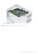
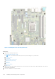
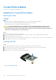
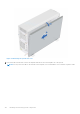
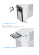
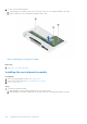
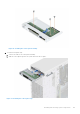
Table Of Contents
- Dell EMC PowerEdge T350 Installation and Service Manual
- Contents
- About this document
- PowerEdge T350 system overview
- Initial system setup and configuration
- Minimum to POST and system management configuration validation
- Installing and removing system components
- Safety instructions
- Before working inside your system
- After working inside your system
- Recommended tools
- Optional front bezel
- System feet
- System cover
- Air shroud
- Intrusion switch module
- Drives
- Removing a drive blank
- Installing a drive blank
- Removing a drive carrier
- Installing the drive carrier
- Removing the drive from the drive carrier
- Installing the drive into the drive carrier
- Removing a 3.5-inch drive adapter from a 3.5-inch drive carrier
- Installing a 3.5-inch adapter into a 3.5-inch drive carrier
- Removing a 2.5-inch drive from the 3.5-inch drive adapter
- Installing a 2.5-inch drive into the 3.5-inch drive adapter
- Optional optical drive
- Drive backplane
- Cooling fans
- Cable routing
- System memory
- Processor and heat sink module
- Expansion cards
- Optional BOSS S2 module
- Optional IDSDM module
- MicroSD card
- Optional internal USB card
- Optional internal USB memory key
- Power supply unit
- Power interposer board
- System battery
- System board
- Trusted Platform Module
- Control panel
- Upgrade Kits
- Jumpers and connectors
- System diagnostics and indicator codes
- Getting help
- Documentation resources

Trusted Platform Module
This is a service technician replaceable part only.
Upgrading the Trusted Platform Module
Removing the TPM
Prerequisites
NOTE:
● Ensure that your operating system supports the version of the TPM module being installed.
● Ensure that you download and install the latest BIOS firmware on your system.
● Ensure that the BIOS is configured to enable UEFI boot mode.
CAUTION: After the TPM plug-in module is installed, it is cryptographically bound to that specific system
board. When the system is powered on, any attempt to remove an installed TPM plug-in module breaks the
cryptographic binding, and the removed TPM cannot be installed on another system board. Ensure any keys you
have stored on the TPM have been securely transferred.
Steps
1. Locate the TPM connector on the system board.
2. Press to hold the module down and remove the screw using the security Torx 8-bit shipped with the TPM module.
3. Slide the TPM module out from its connector.
4. Push the plastic rivet away from the TPM connector and rotate it 90° counterclockwise to release it from the system board.
5. Pull the plastic rivet out of its slot on the system board.
Installing the TPM
Steps
1. To install the TPM, align the edge connectors on the TPM with the slot on the TPM connector.
2. Insert the TPM into the TPM connector such that the plastic rivet aligns with the slot on the system board.
3. Press the plastic rivet until the rivet snaps into place.
4. Replace the screw that secures the TPM to the system board.
Figure 93. Installing the TPM
104
Installing and removing system components