
Installation and Service Manual
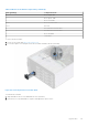
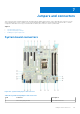
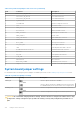
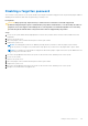
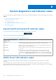
Table Of Contents
- Dell EMC PowerEdge T350 Installation and Service Manual
- Contents
- About this document
- PowerEdge T350 system overview
- Initial system setup and configuration
- Minimum to POST and system management configuration validation
- Installing and removing system components
- Safety instructions
- Before working inside your system
- After working inside your system
- Recommended tools
- Optional front bezel
- System feet
- System cover
- Air shroud
- Intrusion switch module
- Drives
- Removing a drive blank
- Installing a drive blank
- Removing a drive carrier
- Installing the drive carrier
- Removing the drive from the drive carrier
- Installing the drive into the drive carrier
- Removing a 3.5-inch drive adapter from a 3.5-inch drive carrier
- Installing a 3.5-inch adapter into a 3.5-inch drive carrier
- Removing a 2.5-inch drive from the 3.5-inch drive adapter
- Installing a 2.5-inch drive into the 3.5-inch drive adapter
- Optional optical drive
- Drive backplane
- Cooling fans
- Cable routing
- System memory
- Processor and heat sink module
- Expansion cards
- Optional BOSS S2 module
- Optional IDSDM module
- MicroSD card
- Optional internal USB card
- Optional internal USB memory key
- Power supply unit
- Power interposer board
- System battery
- System board
- Trusted Platform Module
- Control panel
- Upgrade Kits
- Jumpers and connectors
- System diagnostics and indicator codes
- Getting help
- Documentation resources

Table 24. System board jumpers and connectors (continued)
Item Connector Description
2 Slot 2: PCIe_G4_X16 CPU PCIe card connector 2
3 Slot 3: PCIe_G3_X1 PCH PCIe card connector 3
4 Slot 4: PCIe_G3_X4 PCH PCIe card connector 4
5 T_INTRUSION Intrusion connector
6 SYSTEM FAN System cooling fan connector
7 CPU Processor socket
8 PWR_CPU 1 CPU power connector P2
9 A3, A1, A4, A2 Memory module sockets
10 PWR_SYSTEM 1 System power connector P1
11 PWR_EVENT1 Power event
12 SATA_ODD/HDD 4 Optical disk drive connector
13 SATA 0-3 Mini SAS connector
14 BOSS_PWR BOSS power connector
15 SL2_PCH_PA2 BOSS signal connector
16 TPM Trusted platform module connector
17 IDSDM/Internal USB connector IDSDM/Internal USB connector
18 BATTERY CMOS Battery connector
19 FP_USB Front panel USB connector
20 CTRL_PNL Control panel
21 PIB connector PIB connector
22 HDD/ODD_POWER Hard drive power connector
23 Jumper NVRAM / Reset BIOS password jumper
System board jumper settings
For information about resetting the password jumper to disable a password, see the Disabling a forgotten password section.
Table 25. System board jumper settings
Jumper Setting Description
PWRD_EN The BIOS password feature is enabled.
The BIOS password feature is disabled. The BIOS password is
now disabled and you are not allowed to set a new password.
NVRAM_CLR The BIOS configuration settings are retained at system boot.
The BIOS configuration settings are cleared at system boot.
CAUTION: Be careful when changing the BIOS settings. The BIOS interface is designed for advanced users. Any
change in the setting could prevent your system from starting correctly and you might have potential loss of
data.
118 Jumpers and connectors