
Installation and Service Manual
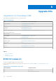
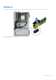
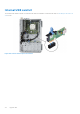
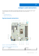
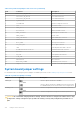
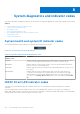
Table Of Contents
- Dell EMC PowerEdge T350 Installation and Service Manual
- Contents
- About this document
- PowerEdge T350 system overview
- Initial system setup and configuration
- Minimum to POST and system management configuration validation
- Installing and removing system components
- Safety instructions
- Before working inside your system
- After working inside your system
- Recommended tools
- Optional front bezel
- System feet
- System cover
- Air shroud
- Intrusion switch module
- Drives
- Removing a drive blank
- Installing a drive blank
- Removing a drive carrier
- Installing the drive carrier
- Removing the drive from the drive carrier
- Installing the drive into the drive carrier
- Removing a 3.5-inch drive adapter from a 3.5-inch drive carrier
- Installing a 3.5-inch adapter into a 3.5-inch drive carrier
- Removing a 2.5-inch drive from the 3.5-inch drive adapter
- Installing a 2.5-inch drive into the 3.5-inch drive adapter
- Optional optical drive
- Drive backplane
- Cooling fans
- Cable routing
- System memory
- Processor and heat sink module
- Expansion cards
- Optional BOSS S2 module
- Optional IDSDM module
- MicroSD card
- Optional internal USB card
- Optional internal USB memory key
- Power supply unit
- Power interposer board
- System battery
- System board
- Trusted Platform Module
- Control panel
- Upgrade Kits
- Jumpers and connectors
- System diagnostics and indicator codes
- Getting help
- Documentation resources

System diagnostics and indicator codes
This section describes the diagnostic indicators on the system front panel that displays the system status during system startup.
Topics:
• System health and system ID indicator codes
• iDRAC Direct LED indicator codes
• NIC indicator codes
• Power supply unit indicator codes
• Non-redundant cabled power supply unit indicator codes
• Drive indicator codes
• Using system diagnostics
System health and system ID indicator codes
The system health and system ID indicator is located on the front panel of the system.
Figure 107. System health and system ID indicator
Table 26. System health and system ID indicator codes
System health and system ID
indicator code
Condition
Solid blue Indicates that the system is powered on, is healthy, and system ID mode is not active.
Press the system health and system ID button to switch to system ID mode.
Blinking blue Indicates that the system ID mode is active. Press the system health and system ID
button to switch to system health mode.
Solid amber Indicates that the system is in fail-safe mode. If the problem persists, see the Getting
help section.
Blinking amber Indicates that the system is experiencing a fault. Check the System Event Log
for specific error messages. For information about the event and error messages
generated by the system firmware and agents that monitor system components, go
to qrl.dell.com > Look Up > Error Code, type the error code, and then click Look it
up.
iDRAC Direct LED indicator codes
The iDRAC Direct LED indicator lights up to indicate that the port is connected and is being used as a part of the iDRAC
subsystem.
You can configure iDRAC Direct by using a USB to micro USB (type AB) cable, which you can connect to your laptop or
tablet. Cable length should not exceed 3 feet (0.91 meters). Performance could be affected by cable quality. The following table
describes iDRAC Direct activity when the iDRAC Direct port is active:
8
120 System diagnostics and indicator codes