
Installation and Service Manual
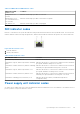
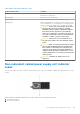
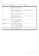
Table Of Contents
- Dell EMC PowerEdge T350 Installation and Service Manual
- Contents
- About this document
- PowerEdge T350 system overview
- Initial system setup and configuration
- Minimum to POST and system management configuration validation
- Installing and removing system components
- Safety instructions
- Before working inside your system
- After working inside your system
- Recommended tools
- Optional front bezel
- System feet
- System cover
- Air shroud
- Intrusion switch module
- Drives
- Removing a drive blank
- Installing a drive blank
- Removing a drive carrier
- Installing the drive carrier
- Removing the drive from the drive carrier
- Installing the drive into the drive carrier
- Removing a 3.5-inch drive adapter from a 3.5-inch drive carrier
- Installing a 3.5-inch adapter into a 3.5-inch drive carrier
- Removing a 2.5-inch drive from the 3.5-inch drive adapter
- Installing a 2.5-inch drive into the 3.5-inch drive adapter
- Optional optical drive
- Drive backplane
- Cooling fans
- Cable routing
- System memory
- Processor and heat sink module
- Expansion cards
- Optional BOSS S2 module
- Optional IDSDM module
- MicroSD card
- Optional internal USB card
- Optional internal USB memory key
- Power supply unit
- Power interposer board
- System battery
- System board
- Trusted Platform Module
- Control panel
- Upgrade Kits
- Jumpers and connectors
- System diagnostics and indicator codes
- Getting help
- Documentation resources

Table 27. iDRAC Direct LED indicator codes
iDRAC Direct LED
indicator code
Condition
Solid green for two
seconds
Indicates that the laptop or tablet is connected.
Blinking green (on for
two seconds and off for
two seconds)
Indicates that the laptop or tablet connected is recognized.
LED Indicator off Indicates that the laptop or tablet is unplugged.
NIC indicator codes
Each NIC on the back of the system has indicators that provide information about the activity and link status. The activity LED
indicator indicates if data is flowing through the NIC, and the link LED indicator indicates the speed of the connected network.
Figure 108. NIC indicator codes
1. Link LED indicator
2. Activity LED indicator
Table 28. NIC indicator codes
NIC indicator codes Condition
Link and activity indicators are off. Indicates that the NIC is not connected to the network.
Link indicator is green, and activity indicator is blinking
green.
Indicates that the NIC is connected to a valid network at its maximum
port speed, and data is being sent or received.
Link indicator is amber, and activity indicator is blinking
green.
Indicates that the NIC is connected to a valid network at less than its
maximum port speed, and data is being sent or received.
Link indicator is green, and activity indicator is off. Indicates that the NIC is connected to a valid network at its maximum
port speed, and data is not being sent or received.
Link indicator is amber, and activity indicator is off. Indicates that the NIC is connected to a valid network at less than its
maximum port speed, and data is not being sent or received.
Link indicator is blinking green, and activity is off. Indicates that the NIC identity is enabled through the NIC
configuration utility.
Power supply unit indicator codes
AC and DC power supply units (PSUs) have an illuminated translucent handle that serves as an indicator. The indicator shows if
power is present or if a power fault has occurred.
System diagnostics and indicator codes
121