
Installation and Service Manual
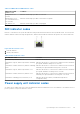
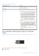
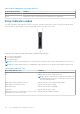
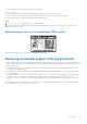
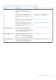
Table Of Contents
- Dell EMC PowerEdge T350 Installation and Service Manual
- Contents
- About this document
- PowerEdge T350 system overview
- Initial system setup and configuration
- Minimum to POST and system management configuration validation
- Installing and removing system components
- Safety instructions
- Before working inside your system
- After working inside your system
- Recommended tools
- Optional front bezel
- System feet
- System cover
- Air shroud
- Intrusion switch module
- Drives
- Removing a drive blank
- Installing a drive blank
- Removing a drive carrier
- Installing the drive carrier
- Removing the drive from the drive carrier
- Installing the drive into the drive carrier
- Removing a 3.5-inch drive adapter from a 3.5-inch drive carrier
- Installing a 3.5-inch adapter into a 3.5-inch drive carrier
- Removing a 2.5-inch drive from the 3.5-inch drive adapter
- Installing a 2.5-inch drive into the 3.5-inch drive adapter
- Optional optical drive
- Drive backplane
- Cooling fans
- Cable routing
- System memory
- Processor and heat sink module
- Expansion cards
- Optional BOSS S2 module
- Optional IDSDM module
- MicroSD card
- Optional internal USB card
- Optional internal USB memory key
- Power supply unit
- Power interposer board
- System battery
- System board
- Trusted Platform Module
- Control panel
- Upgrade Kits
- Jumpers and connectors
- System diagnostics and indicator codes
- Getting help
- Documentation resources

Table 31. Non-redundant AC PSU status indicator
Power Indicator Pattern Condition
Not lit Power is not connected or PSU is faulty.
Green A valid power source is connected to the PSU and the PSU is operational.
Drive indicator codes
The LEDs on the drive carrier indicate the state of each drive. Each drive carrier has two LEDs: an activity LED (green) and a
status LED (bicolor, green/amber). The activity LED blinks whenever the drive is accessed.
Figure 111. Drive indicators on the drive and the mid drive tray backplane
1. Drive activity LED indicator
2. Drive status LED indicator
3. Drive capacity label
NOTE: If the drive is in the Advanced Host Controller Interface (AHCI) mode, the status LED indicator does not power on.
NOTE: Drive status indicator behavior is managed by Storage Spaces Direct. Not all drive status indicators may be used.
Table 32. Drive indicator codes
Drive status indicator code Condition
Blinks green twice per second Indicates that the drive is being identified or preparing for removal.
Off Indicates that the drive is ready for removal.
NOTE: The drive status indicator remains off until all drives are
initialized after the system is powered on. Drives are not ready
for removal during this time.
Blinks green, amber, and then powers off Indicates that there is an unexpected drive failure.
Blinks amber four times per second Indicates that the drive has failed.
Blinks green slowly Indicates that the drive is rebuilding.
Solid green Indicates that the drive is online.
Blinks green for three seconds, amber for three seconds,
and then powers off after six seconds
Indicates that the rebuild has stopped.
124 System diagnostics and indicator codes