
Installation and Service Manual
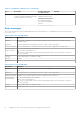
Table Of Contents
- Dell EMC PowerEdge T350 Installation and Service Manual
- Contents
- About this document
- PowerEdge T350 system overview
- Initial system setup and configuration
- Minimum to POST and system management configuration validation
- Installing and removing system components
- Safety instructions
- Before working inside your system
- After working inside your system
- Recommended tools
- Optional front bezel
- System feet
- System cover
- Air shroud
- Intrusion switch module
- Drives
- Removing a drive blank
- Installing a drive blank
- Removing a drive carrier
- Installing the drive carrier
- Removing the drive from the drive carrier
- Installing the drive into the drive carrier
- Removing a 3.5-inch drive adapter from a 3.5-inch drive carrier
- Installing a 3.5-inch adapter into a 3.5-inch drive carrier
- Removing a 2.5-inch drive from the 3.5-inch drive adapter
- Installing a 2.5-inch drive into the 3.5-inch drive adapter
- Optional optical drive
- Drive backplane
- Cooling fans
- Cable routing
- System memory
- Processor and heat sink module
- Expansion cards
- Optional BOSS S2 module
- Optional IDSDM module
- MicroSD card
- Optional internal USB card
- Optional internal USB memory key
- Power supply unit
- Power interposer board
- System battery
- System board
- Trusted Platform Module
- Control panel
- Upgrade Kits
- Jumpers and connectors
- System diagnostics and indicator codes
- Getting help
- Documentation resources

Minimum to POST and system management
configuration validation
This section describes the minimum to POST system requirement and system management configuration validation of the Dell
EMC system.
Topics:
• Minimum configuration to POST
• Configuration validation
Minimum configuration to POST
The components listed below are the minimum configuration to POST:
● Processor
● One memory module (DIMM) in socket A1
● One power supply unit
● System board
Configuration validation
The new generation of PowerEdge systems have added interconnect flexibility and advanced iDRAC management features to
collect precise system configuration information and report configuration errors.
When the system is powered on, information about installed cables, backplanes, floating card (like BOSS), and processor is
obtained from the CPLD and backplane memory maps is analyzed. This information forms a unique configuration, which is
compared with one of the qualified configurations stored in a table maintained by iDRAC.
One or more sensors are assigned to each of the configuration elements. During POST, any configuration validation error is
logged in the System Event Log (SEL)/LifeCycle (LC) log. The reported events are categorized in the configuration validation
error table.
Table 9. Configuration validation error
Error Description Possible cause and
recommendations
Example
Config Error A configuration element within the
closest match contains something that is
unexpected and does not match any Dell
qualified configuration.
Wrong configuration Config Error: Backplane cable
CTRS_SRC_SA1 and BP-DST_SA1
The element reported
in HWC8010 errors are
assembled incorrectly.
Verify element (cable, etc)
placement in the system.
Config Error : SL Cable
PLANAR_SL7 and CTRL_DST_PA1
Config
Missing
iDRAC found a configuration element
missing within the closest match
detected.
Missing or damaged cable,
device, or part
Config Missing: adapter PERC/HBA
Missing element or cable
is reported in HWC8010
error logs. Install the
missing element (cable,
etc).
Config Missing : SL cable
PLANAR_SL8 and CTRL_DST_PA1
4
Minimum to POST and system management configuration validation 25