
Installation and Service Manual
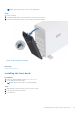
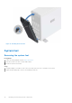
Table Of Contents
- Dell EMC PowerEdge T350 Installation and Service Manual
- Contents
- About this document
- PowerEdge T350 system overview
- Initial system setup and configuration
- Minimum to POST and system management configuration validation
- Installing and removing system components
- Safety instructions
- Before working inside your system
- After working inside your system
- Recommended tools
- Optional front bezel
- System feet
- System cover
- Air shroud
- Intrusion switch module
- Drives
- Removing a drive blank
- Installing a drive blank
- Removing a drive carrier
- Installing the drive carrier
- Removing the drive from the drive carrier
- Installing the drive into the drive carrier
- Removing a 3.5-inch drive adapter from a 3.5-inch drive carrier
- Installing a 3.5-inch adapter into a 3.5-inch drive carrier
- Removing a 2.5-inch drive from the 3.5-inch drive adapter
- Installing a 2.5-inch drive into the 3.5-inch drive adapter
- Optional optical drive
- Drive backplane
- Cooling fans
- Cable routing
- System memory
- Processor and heat sink module
- Expansion cards
- Optional BOSS S2 module
- Optional IDSDM module
- MicroSD card
- Optional internal USB card
- Optional internal USB memory key
- Power supply unit
- Power interposer board
- System battery
- System board
- Trusted Platform Module
- Control panel
- Upgrade Kits
- Jumpers and connectors
- System diagnostics and indicator codes
- Getting help
- Documentation resources

NOTE: While replacing faulty storage controller, FC, or NIC card with the same type of card, after you power on the
system; the new card automatically updates to the same firmware and configuration of the faulty one. For more information
about the Part replacement configuration, see the Lifecycle Controller User's Guide at https://www.dell.com/idracmanuals.
CAUTION: Do not install GPUs, network cards, or other PCIe devices on your system that are not validated
and tested by Dell. Damage caused by unauthorized and invalidated hardware installation will null and void the
system warranty.
Before working inside your system
Prerequisites
Follow the safety guidelines listed in the Safety instructions.
Steps
1. Power off the system and all attached peripherals.
2. Disconnect the system from the electrical outlet, and disconnect the peripherals.
3. Remove the system cover.
After working inside your system
Prerequisites
Follow the safety guidelines listed in Safety instructions.
Steps
1. Replace the system cover.
2. Reconnect the peripherals and connect the system to the electrical outlet, and then power on the system.
Recommended tools
You need the following tools to perform the removal and installation procedures:
● Key to the bezel lock. The key is required only if your system includes a bezel.
● Phillips 1 screwdriver
● Phillips 2 screwdriver
● Torx T15 screwdriver
● 5 mm hex nut screwdriver
● Plastic scribe
● 1/4-inch flat blade screwdriver
● Wrist grounding strap connected to the ground
● ESD mat
● Needle-nose pliers
Optional front bezel
Removing the front bezel
Prerequisites
1. Follow the safety guidelines listed in Safety instructions.
2. Keep the bezel key handy.
28
Installing and removing system components