
Installation and Service Manual
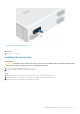
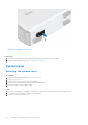
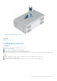
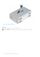
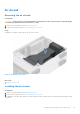
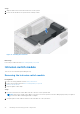
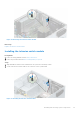
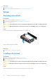
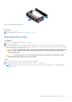
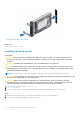
Table Of Contents
- Dell EMC PowerEdge T350 Installation and Service Manual
- Contents
- About this document
- PowerEdge T350 system overview
- Initial system setup and configuration
- Minimum to POST and system management configuration validation
- Installing and removing system components
- Safety instructions
- Before working inside your system
- After working inside your system
- Recommended tools
- Optional front bezel
- System feet
- System cover
- Air shroud
- Intrusion switch module
- Drives
- Removing a drive blank
- Installing a drive blank
- Removing a drive carrier
- Installing the drive carrier
- Removing the drive from the drive carrier
- Installing the drive into the drive carrier
- Removing a 3.5-inch drive adapter from a 3.5-inch drive carrier
- Installing a 3.5-inch adapter into a 3.5-inch drive carrier
- Removing a 2.5-inch drive from the 3.5-inch drive adapter
- Installing a 2.5-inch drive into the 3.5-inch drive adapter
- Optional optical drive
- Drive backplane
- Cooling fans
- Cable routing
- System memory
- Processor and heat sink module
- Expansion cards
- Optional BOSS S2 module
- Optional IDSDM module
- MicroSD card
- Optional internal USB card
- Optional internal USB memory key
- Power supply unit
- Power interposer board
- System battery
- System board
- Trusted Platform Module
- Control panel
- Upgrade Kits
- Jumpers and connectors
- System diagnostics and indicator codes
- Getting help
- Documentation resources

Figure 16. Removing the system cover
Next steps
Replace the system cover.
Installing the system cover
Prerequisites
1. Follow the safety guidelines listed in Safety instructions.
2. Remove the front bezel.
3. Power off the system and any attached peripherals.
4. Disconnect the system from the electrical outlet and peripherals.
5. Ensure that all internal cables are connected and placed out of the way and no tools or extra parts are left inside the system.
Steps
1. Align the tabs on the system cover with the guide slots on the system and slide the system cover.
2. Close the system cover release latch.
3. Using a 1/4-inch flat head or a Phillips 2 screwdriver, turn the lock clockwise to the locked position.
Installing and removing system components
33