
Installation and Service Manual
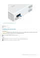
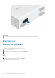
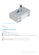
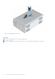
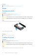
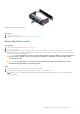
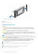
Table Of Contents
- Dell EMC PowerEdge T350 Installation and Service Manual
- Contents
- About this document
- PowerEdge T350 system overview
- Initial system setup and configuration
- Minimum to POST and system management configuration validation
- Installing and removing system components
- Safety instructions
- Before working inside your system
- After working inside your system
- Recommended tools
- Optional front bezel
- System feet
- System cover
- Air shroud
- Intrusion switch module
- Drives
- Removing a drive blank
- Installing a drive blank
- Removing a drive carrier
- Installing the drive carrier
- Removing the drive from the drive carrier
- Installing the drive into the drive carrier
- Removing a 3.5-inch drive adapter from a 3.5-inch drive carrier
- Installing a 3.5-inch adapter into a 3.5-inch drive carrier
- Removing a 2.5-inch drive from the 3.5-inch drive adapter
- Installing a 2.5-inch drive into the 3.5-inch drive adapter
- Optional optical drive
- Drive backplane
- Cooling fans
- Cable routing
- System memory
- Processor and heat sink module
- Expansion cards
- Optional BOSS S2 module
- Optional IDSDM module
- MicroSD card
- Optional internal USB card
- Optional internal USB memory key
- Power supply unit
- Power interposer board
- System battery
- System board
- Trusted Platform Module
- Control panel
- Upgrade Kits
- Jumpers and connectors
- System diagnostics and indicator codes
- Getting help
- Documentation resources

Figure 24. Removing a drive carrier
Next steps
Replace the drive or a drive blank.
Installing the drive carrier
Prerequisites
CAUTION:
Before removing or installing a drive while the system is running, see the documentation for the
storage controller card to ensure that the host adapter is configured correctly to support drive removal and
insertion.
CAUTION: Combining SAS and SATA drives in the same RAID volume is not supported.
CAUTION: When installing a drive, ensure that the adjacent drives are fully installed. Inserting a drive carrier
and attempting to lock its handle next to a partially installed carrier can damage the partially installed carrier's
shield spring and make it unusable.
NOTE: Ensure that the drive carrier's release handle is in the open position before inserting the carrier into the slot.
CAUTION: To prevent data loss, ensure that your operating system supports hot-swap drive installation. See the
documentation supplied with your operating system.
CAUTION: When a replacement hot swappable drive is installed and the system is powered on, the drive
automatically begins to rebuild. Ensure that the replacement drive is blank or contains data that you wish to
overwrite. Any data on the replacement drive is immediately lost after the drive is installed.
1. Follow the safety guidelines listed in Safety instructions.
2. Remove the front bezel.
3. Remove the drive carrier or remove the drive blank when you want to assemble the drives in to the system.
Steps
1. Slide the drive carrier into the drive slot and push until the drive connects with the backplane.
2. Close the drive carrier release handle to lock the drive in place.
40
Installing and removing system components