
Installation and Service Manual
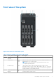
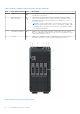
Table Of Contents
- Dell EMC PowerEdge T350 Installation and Service Manual
- Contents
- About this document
- PowerEdge T350 system overview
- Initial system setup and configuration
- Minimum to POST and system management configuration validation
- Installing and removing system components
- Safety instructions
- Before working inside your system
- After working inside your system
- Recommended tools
- Optional front bezel
- System feet
- System cover
- Air shroud
- Intrusion switch module
- Drives
- Removing a drive blank
- Installing a drive blank
- Removing a drive carrier
- Installing the drive carrier
- Removing the drive from the drive carrier
- Installing the drive into the drive carrier
- Removing a 3.5-inch drive adapter from a 3.5-inch drive carrier
- Installing a 3.5-inch adapter into a 3.5-inch drive carrier
- Removing a 2.5-inch drive from the 3.5-inch drive adapter
- Installing a 2.5-inch drive into the 3.5-inch drive adapter
- Optional optical drive
- Drive backplane
- Cooling fans
- Cable routing
- System memory
- Processor and heat sink module
- Expansion cards
- Optional BOSS S2 module
- Optional IDSDM module
- MicroSD card
- Optional internal USB card
- Optional internal USB memory key
- Power supply unit
- Power interposer board
- System battery
- System board
- Trusted Platform Module
- Control panel
- Upgrade Kits
- Jumpers and connectors
- System diagnostics and indicator codes
- Getting help
- Documentation resources
Installing the MicroSD card....................................................................................................................................... 84
Optional internal USB card............................................................................................................................................. 85
Removing the internal USB card............................................................................................................................. 85
Installing the internal USB card................................................................................................................................86
Optional internal USB memory key............................................................................................................................... 87
Removing the internal USB memory key............................................................................................................... 87
Installing the internal USB memory key ................................................................................................................ 87
Power supply unit..............................................................................................................................................................88
Hot spare feature........................................................................................................................................................ 88
Removing a power supply unit blank...................................................................................................................... 88
Installing a power supply unit blank........................................................................................................................ 89
Removing a power supply unit................................................................................................................................. 89
Installing a power supply unit................................................................................................................................... 90
Removing a cabled PSU............................................................................................................................................. 91
Installing the cabled PSU...........................................................................................................................................93
Power interposer board................................................................................................................................................... 94
Removing the power interposer board...................................................................................................................94
Installing the power interposer board.....................................................................................................................95
System battery ................................................................................................................................................................. 96
Replacing the system battery.................................................................................................................................. 96
System board..................................................................................................................................................................... 98
Removing the system board..................................................................................................................................... 98
Installing the system board..................................................................................................................................... 100
Trusted Platform Module...............................................................................................................................................104
Upgrading the Trusted Platform Module............................................................................................................. 104
Initializing TPM for users......................................................................................................................................... 105
Initializing the TPM 1.2 for users............................................................................................................................105
Initializing the TPM 2.0 for users...........................................................................................................................105
Control panel.................................................................................................................................................................... 105
Removing the control panel assembly.................................................................................................................. 105
Installing the control panel assembly.................................................................................................................... 108
Chapter 6: Upgrade Kits............................................................................................................. 112
BOSS S2 module kit.........................................................................................................................................................112
IDSDM kit........................................................................................................................................................................... 115
Internal USB card kit........................................................................................................................................................116
Chapter 7: Jumpers and connectors............................................................................................117
System board connectors...............................................................................................................................................117
System board jumper settings.......................................................................................................................................118
Disabling a forgotten password.................................................................................................................................... 119
Chapter 8: System diagnostics and indicator codes................................................................... 120
System health and system ID indicator codes..........................................................................................................120
iDRAC Direct LED indicator codes.............................................................................................................................. 120
NIC indicator codes..........................................................................................................................................................121
Power supply unit indicator codes............................................................................................................................... 121
Non-redundant cabled power supply unit indicator codes.................................................................................... 123
Drive indicator codes...................................................................................................................................................... 124
Contents
5