
Installation and Service Manual
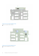
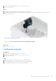
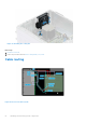
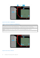
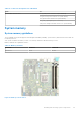
Table Of Contents
- Dell EMC PowerEdge T350 Installation and Service Manual
- Contents
- About this document
- PowerEdge T350 system overview
- Initial system setup and configuration
- Minimum to POST and system management configuration validation
- Installing and removing system components
- Safety instructions
- Before working inside your system
- After working inside your system
- Recommended tools
- Optional front bezel
- System feet
- System cover
- Air shroud
- Intrusion switch module
- Drives
- Removing a drive blank
- Installing a drive blank
- Removing a drive carrier
- Installing the drive carrier
- Removing the drive from the drive carrier
- Installing the drive into the drive carrier
- Removing a 3.5-inch drive adapter from a 3.5-inch drive carrier
- Installing a 3.5-inch adapter into a 3.5-inch drive carrier
- Removing a 2.5-inch drive from the 3.5-inch drive adapter
- Installing a 2.5-inch drive into the 3.5-inch drive adapter
- Optional optical drive
- Drive backplane
- Cooling fans
- Cable routing
- System memory
- Processor and heat sink module
- Expansion cards
- Optional BOSS S2 module
- Optional IDSDM module
- MicroSD card
- Optional internal USB card
- Optional internal USB memory key
- Power supply unit
- Power interposer board
- System battery
- System board
- Trusted Platform Module
- Control panel
- Upgrade Kits
- Jumpers and connectors
- System diagnostics and indicator codes
- Getting help
- Documentation resources

Table 13. Connector descriptions for 8 x 3.5-inch drive system
From To
CTRL_SRC_SA1 (backplane controller connector on system
board)
BP_DST_SA1 (backplane signal connector)
BOSS_PWR (BOSS S2 module power connector on system
board)
PWR_1 (BOSS S2 module power connector)
SL2_PCH_PA2 (signal connector on system board) PCIe_1 (BOSS S2 module signal connector)
SATA_ODD (optical disc drive SATA connector on system
board) and HDD/ODD_PWR (optical disk drive power
connector on system board)
ODD (optical disc drive connector)
FP_USB (front USB connector on system board) and
CTRL_PNL (control panel connector on system board)
FIO (control panel connector)
Figure 43. Cable routing - 4 x 3.5-inch drive system
Table 14. Connector descriptions for 4 x 3.5-inch drive system
From To
SL1_PCH_SA1 (backplane signal connector on system board) BP_DST_SA1 (backplane signal connector)
BOSS_PWR (BOSS S2 module power connector on system
board)
PWR_1 (BOSS S2 module power connector)
SL2_PCH_PA2 (signal connector on system board) PCIe_1 (BOSS S2 module signal connector)
SATA_ODD (optical disc drive SATA connector on system
board) and HDD/ODD_PWR (optical disk drive power
connector on system board)
ODD (optical disc drive connector)
FP_USB (front USB connector on system board) and
CTRL_PNL (control panel connector on system board)
FIO (control panel connector)
Installing and removing system components 57