
Installation and Service Manual
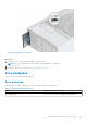
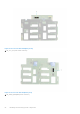
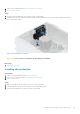
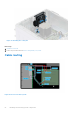
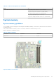
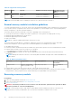
Table Of Contents
- Dell EMC PowerEdge T350 Installation and Service Manual
- Contents
- About this document
- PowerEdge T350 system overview
- Initial system setup and configuration
- Minimum to POST and system management configuration validation
- Installing and removing system components
- Safety instructions
- Before working inside your system
- After working inside your system
- Recommended tools
- Optional front bezel
- System feet
- System cover
- Air shroud
- Intrusion switch module
- Drives
- Removing a drive blank
- Installing a drive blank
- Removing a drive carrier
- Installing the drive carrier
- Removing the drive from the drive carrier
- Installing the drive into the drive carrier
- Removing a 3.5-inch drive adapter from a 3.5-inch drive carrier
- Installing a 3.5-inch adapter into a 3.5-inch drive carrier
- Removing a 2.5-inch drive from the 3.5-inch drive adapter
- Installing a 2.5-inch drive into the 3.5-inch drive adapter
- Optional optical drive
- Drive backplane
- Cooling fans
- Cable routing
- System memory
- Processor and heat sink module
- Expansion cards
- Optional BOSS S2 module
- Optional IDSDM module
- MicroSD card
- Optional internal USB card
- Optional internal USB memory key
- Power supply unit
- Power interposer board
- System battery
- System board
- Trusted Platform Module
- Control panel
- Upgrade Kits
- Jumpers and connectors
- System diagnostics and indicator codes
- Getting help
- Documentation resources

Table 16. Connector descriptions for cabled PSU
From To
Power cables from the PSU P1 (system power connector on system board)
P2 (processor power connector on system board)
P3 ( power event connector on system board)
BP_PWR_1 (backplane power connector)
PIB (Power interposer board connector on system board)
System memory
System memory guidelines
The PowerEdge T350 system supports DDR4 unregistered DIMMs (UDIMMs). System memory holds the instructions that are
run by the processor.
Your system contains four memory sockets. Two memory channels are allocated to the processor.
Memory channels are organized as follows:
Table 17. Memory channels
Processor Channel A Channel B
Processor 1 A1, A3 A2, A4
Figure 46. Memory socket location
Installing and removing system components
59