
Installation and Service Manual
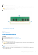
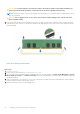
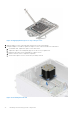
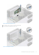
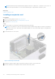
Table Of Contents
- Dell EMC PowerEdge T350 Installation and Service Manual
- Contents
- About this document
- PowerEdge T350 system overview
- Initial system setup and configuration
- Minimum to POST and system management configuration validation
- Installing and removing system components
- Safety instructions
- Before working inside your system
- After working inside your system
- Recommended tools
- Optional front bezel
- System feet
- System cover
- Air shroud
- Intrusion switch module
- Drives
- Removing a drive blank
- Installing a drive blank
- Removing a drive carrier
- Installing the drive carrier
- Removing the drive from the drive carrier
- Installing the drive into the drive carrier
- Removing a 3.5-inch drive adapter from a 3.5-inch drive carrier
- Installing a 3.5-inch adapter into a 3.5-inch drive carrier
- Removing a 2.5-inch drive from the 3.5-inch drive adapter
- Installing a 2.5-inch drive into the 3.5-inch drive adapter
- Optional optical drive
- Drive backplane
- Cooling fans
- Cable routing
- System memory
- Processor and heat sink module
- Expansion cards
- Optional BOSS S2 module
- Optional IDSDM module
- MicroSD card
- Optional internal USB card
- Optional internal USB memory key
- Power supply unit
- Power interposer board
- System battery
- System board
- Trusted Platform Module
- Control panel
- Upgrade Kits
- Jumpers and connectors
- System diagnostics and indicator codes
- Getting help
- Documentation resources

Steps
1. Locate the appropriate memory module socket.
2. To release the memory module from the socket, simultaneously press the ejectors on both ends of the memory module
socket to fully open.
CAUTION: Handle each memory module only by the card edges, ensuring not to touch the middle of the
memory module or metallic contacts.
3. Lift the memory module away from the system.
Figure 47. Removing a memory module
Next steps
Replace the memory module.
Installing a memory module
Prerequisites
1. Follow the safety guidelines listed in the Safety instructions.
2. Follow the procedure listed in the Before working inside your system.
3. Remove the air shroud.
Steps
1. Locate the appropriate memory module socket.
CAUTION:
Handle each memory module only by the card edges, ensuring not to touch the middle of the
memory module or metallic contacts.
2. If a memory module is installed in the socket, remove it.
NOTE: Ensure the socket ejector latches are fully open, before installing the memory module.
3. Align the edge connector of the memory module with the alignment key of the memory module socket, and insert the
memory module in the socket.
Installing and removing system components
61