
Installation and Service Manual
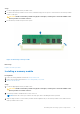
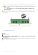
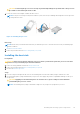
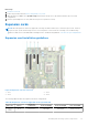
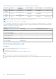
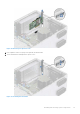
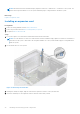
Table Of Contents
- Dell EMC PowerEdge T350 Installation and Service Manual
- Contents
- About this document
- PowerEdge T350 system overview
- Initial system setup and configuration
- Minimum to POST and system management configuration validation
- Installing and removing system components
- Safety instructions
- Before working inside your system
- After working inside your system
- Recommended tools
- Optional front bezel
- System feet
- System cover
- Air shroud
- Intrusion switch module
- Drives
- Removing a drive blank
- Installing a drive blank
- Removing a drive carrier
- Installing the drive carrier
- Removing the drive from the drive carrier
- Installing the drive into the drive carrier
- Removing a 3.5-inch drive adapter from a 3.5-inch drive carrier
- Installing a 3.5-inch adapter into a 3.5-inch drive carrier
- Removing a 2.5-inch drive from the 3.5-inch drive adapter
- Installing a 2.5-inch drive into the 3.5-inch drive adapter
- Optional optical drive
- Drive backplane
- Cooling fans
- Cable routing
- System memory
- Processor and heat sink module
- Expansion cards
- Optional BOSS S2 module
- Optional IDSDM module
- MicroSD card
- Optional internal USB card
- Optional internal USB memory key
- Power supply unit
- Power interposer board
- System battery
- System board
- Trusted Platform Module
- Control panel
- Upgrade Kits
- Jumpers and connectors
- System diagnostics and indicator codes
- Getting help
- Documentation resources

Next steps
1. Install the air shroud.
2. Follow the procedure listed in After working inside your system.
3. While booting, press F2 to enter System Setup and check that the processor information matches the new system
configuration.
4. Run the system diagnostics to verify that the new processor operates correctly.
Expansion cards
NOTE: When an expansion card is not supported or missing, the iDRAC and Lifecycle Controller logs an event. This does
not prevent your system from booting. However, if a F1/F2 pause occurs with an error message, see Troubleshooting
expansion cards section in the Dell EMC PowerEdge Servers Troubleshooting Guide at www.dell.com/poweredgemanuals.
Expansion card installation guidelines
Figure 54. Expansion card slot connectors
1.
Slot 1 2. Slot 2
3. Slot 3 4. Slot 4
The following table describes the expansion card riser configurations:
Table 20. Expansion card slots supported on the system board
PCIe slot Risers
Processor
connection
PCIe slot height PCIe slot length PCIe slot width
Slot 1
(Gen4)
N/A Processor 1 Full height Half length x4 link in x8 slot
Installing and removing system components 67