
Installation and Service Manual
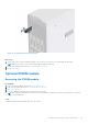
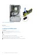
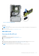
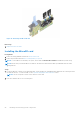
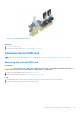
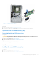
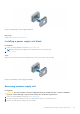
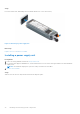
Table Of Contents
- Dell EMC PowerEdge T350 Installation and Service Manual
- Contents
- About this document
- PowerEdge T350 system overview
- Initial system setup and configuration
- Minimum to POST and system management configuration validation
- Installing and removing system components
- Safety instructions
- Before working inside your system
- After working inside your system
- Recommended tools
- Optional front bezel
- System feet
- System cover
- Air shroud
- Intrusion switch module
- Drives
- Removing a drive blank
- Installing a drive blank
- Removing a drive carrier
- Installing the drive carrier
- Removing the drive from the drive carrier
- Installing the drive into the drive carrier
- Removing a 3.5-inch drive adapter from a 3.5-inch drive carrier
- Installing a 3.5-inch adapter into a 3.5-inch drive carrier
- Removing a 2.5-inch drive from the 3.5-inch drive adapter
- Installing a 2.5-inch drive into the 3.5-inch drive adapter
- Optional optical drive
- Drive backplane
- Cooling fans
- Cable routing
- System memory
- Processor and heat sink module
- Expansion cards
- Optional BOSS S2 module
- Optional IDSDM module
- MicroSD card
- Optional internal USB card
- Optional internal USB memory key
- Power supply unit
- Power interposer board
- System battery
- System board
- Trusted Platform Module
- Control panel
- Upgrade Kits
- Jumpers and connectors
- System diagnostics and indicator codes
- Getting help
- Documentation resources

Figure 72. Installing the IDSDM module
Next steps
1. Install the MicroSD cards.
NOTE: Reinstall the MicroSD cards into the same slots based on the labels you had marked on the cards during removal.
2. Install the air shroud.
3. Follow the procedure listed in the After working inside your system.
MicroSD card
Removing the MicroSD card
Prerequisites
1. Follow the safety guidelines listed in the Safety instructions.
2. Follow the procedure listed in the Before working inside your system.
3. Remove the IDSDM module.
Steps
1. Locate the MicroSD card slot on the IDSDM module, and press the card to partially release it from the slot. For more
information on the IDSDM module location, see System board jumpers and connectors section.
2. Hold the MicroSD card, and remove them from the IDSDM module.
NOTE: Temporarily label each MicroSD card with the corresponding slot number after removal.
Installing and removing system components 83