
Installation and Service Manual
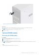
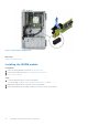
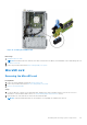
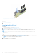
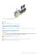
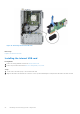
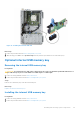
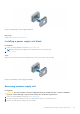
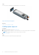
Table Of Contents
- Dell EMC PowerEdge T350 Installation and Service Manual
- Contents
- About this document
- PowerEdge T350 system overview
- Initial system setup and configuration
- Minimum to POST and system management configuration validation
- Installing and removing system components
- Safety instructions
- Before working inside your system
- After working inside your system
- Recommended tools
- Optional front bezel
- System feet
- System cover
- Air shroud
- Intrusion switch module
- Drives
- Removing a drive blank
- Installing a drive blank
- Removing a drive carrier
- Installing the drive carrier
- Removing the drive from the drive carrier
- Installing the drive into the drive carrier
- Removing a 3.5-inch drive adapter from a 3.5-inch drive carrier
- Installing a 3.5-inch adapter into a 3.5-inch drive carrier
- Removing a 2.5-inch drive from the 3.5-inch drive adapter
- Installing a 2.5-inch drive into the 3.5-inch drive adapter
- Optional optical drive
- Drive backplane
- Cooling fans
- Cable routing
- System memory
- Processor and heat sink module
- Expansion cards
- Optional BOSS S2 module
- Optional IDSDM module
- MicroSD card
- Optional internal USB card
- Optional internal USB memory key
- Power supply unit
- Power interposer board
- System battery
- System board
- Trusted Platform Module
- Control panel
- Upgrade Kits
- Jumpers and connectors
- System diagnostics and indicator codes
- Getting help
- Documentation resources

Steps
Connect the USB memory key into the USB port.
Next steps
1. Follow the procedure listed in After working inside your system.
2. While booting, press F2 to enter System Setup and verify that the system detects the USB memory key.
Power supply unit
NOTE: While replacing the hot swappable PSU, after next server boot; the new PSU automatically updates to the same
firmware and configuration of the replaced one. For more information about the Part replacement configuration, see the
Lifecycle Controller User's Guide at https://www.dell.com/idracmanuals.
Hot spare feature
Your system supports the hot spare feature that significantly reduces the power overhead associated with the power supply
unit (PSU) redundancy.
When the hot spare feature is enabled, one of the redundant PSUs is switched to the sleep state. The active PSU supports 100
percent of the system load, thus operating at higher efficiency. The PSU in the sleep state monitors output voltage of the active
PSU. If the output voltage of the active PSU drops, the PSU in the sleep state returns to an active output state.
If having both PSUs active is more efficient than having one PSU in the sleep state, the active PSU can also activate the
sleeping PSU.
The default PSU settings are as follows:
● If the load on the active PSU is more than 50 percent of PSU rated power wattage, then the redundant PSU is switched to
the active state.
● If the load on the active PSU falls below 20 percent of PSU rated power wattage, then the redundant PSU is switched to
the sleep state.
You can configure the hot spare feature by using the iDRAC settings. For more information, see the iDRAC User’s Guide
available at www.dell.com/poweredgemanuals.
Removing a power supply unit blank
Prerequisites
Follow the safety guidelines listed in the Safety instructions.
Steps
Pull the blank out of the system.
CAUTION:
For proper system cooling, the PSU blank must be installed in the second PSU bay in a non-redundant
configuration. Remove the PSU blank only if you are installing a second PSU.
88 Installing and removing system components