
Installation and Service Manual
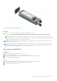
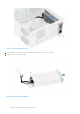
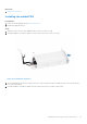
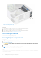
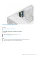
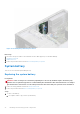
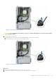
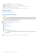
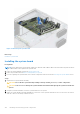
Table Of Contents
- Dell EMC PowerEdge T350 Installation and Service Manual
- Contents
- About this document
- PowerEdge T350 system overview
- Initial system setup and configuration
- Minimum to POST and system management configuration validation
- Installing and removing system components
- Safety instructions
- Before working inside your system
- After working inside your system
- Recommended tools
- Optional front bezel
- System feet
- System cover
- Air shroud
- Intrusion switch module
- Drives
- Removing a drive blank
- Installing a drive blank
- Removing a drive carrier
- Installing the drive carrier
- Removing the drive from the drive carrier
- Installing the drive into the drive carrier
- Removing a 3.5-inch drive adapter from a 3.5-inch drive carrier
- Installing a 3.5-inch adapter into a 3.5-inch drive carrier
- Removing a 2.5-inch drive from the 3.5-inch drive adapter
- Installing a 2.5-inch drive into the 3.5-inch drive adapter
- Optional optical drive
- Drive backplane
- Cooling fans
- Cable routing
- System memory
- Processor and heat sink module
- Expansion cards
- Optional BOSS S2 module
- Optional IDSDM module
- MicroSD card
- Optional internal USB card
- Optional internal USB memory key
- Power supply unit
- Power interposer board
- System battery
- System board
- Trusted Platform Module
- Control panel
- Upgrade Kits
- Jumpers and connectors
- System diagnostics and indicator codes
- Getting help
- Documentation resources

Figure 80. Installing a power supply unit
Next steps
1. Connect the power cable to the PSU, and plug the cable into a power outlet.
CAUTION: When connecting the power cable to the PSU, secure the cable to the PSU with the strap.
NOTE: When installing, hot swapping, or hot adding a new PSU, wait for 15 seconds for the system to recognize the
PSU and determine its status. The PSU redundancy may not occur until discovery is complete. The PSU status indicator
turns green to indicate that the PSU is functioning properly.
NOTE: For certain premium configurations with high power consumption, system PSU might stay with 2+0 mode only, 1+1
redundant mode is not available.
NOTE: While replacing the hot swappable PSU, after next server boot; the new PSU automatically updates to the same
firmware and configuration of the replaced one. For more information about the Part replacement configuration, see the
Lifecycle Controller User's Guide at https://www.dell.com/idracmanuals.
Removing a cabled PSU
Prerequisites
1. Follow the safety guidelines listed in Safety instructions.
2. Follow the procedure listed in Before working inside your system.
3. Disconnect the power cables of the PSU from the system board and the drive backplane.
4. Remove the cables from the cable clip.
Steps
1. Using a Phillips 2 screwdriver, remove the screws that secure the PSU cage to the system.
2. Tilt at an angle and slide the PSU cage towards the front of the system.
3. Lift the PSU cage out of the system.
Installing and removing system components
91