
Installation and Service Manual
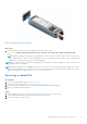
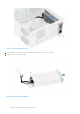
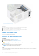
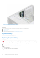
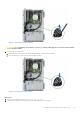
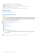
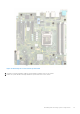
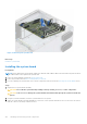
Table Of Contents
- Dell EMC PowerEdge T350 Installation and Service Manual
- Contents
- About this document
- PowerEdge T350 system overview
- Initial system setup and configuration
- Minimum to POST and system management configuration validation
- Installing and removing system components
- Safety instructions
- Before working inside your system
- After working inside your system
- Recommended tools
- Optional front bezel
- System feet
- System cover
- Air shroud
- Intrusion switch module
- Drives
- Removing a drive blank
- Installing a drive blank
- Removing a drive carrier
- Installing the drive carrier
- Removing the drive from the drive carrier
- Installing the drive into the drive carrier
- Removing a 3.5-inch drive adapter from a 3.5-inch drive carrier
- Installing a 3.5-inch adapter into a 3.5-inch drive carrier
- Removing a 2.5-inch drive from the 3.5-inch drive adapter
- Installing a 2.5-inch drive into the 3.5-inch drive adapter
- Optional optical drive
- Drive backplane
- Cooling fans
- Cable routing
- System memory
- Processor and heat sink module
- Expansion cards
- Optional BOSS S2 module
- Optional IDSDM module
- MicroSD card
- Optional internal USB card
- Optional internal USB memory key
- Power supply unit
- Power interposer board
- System battery
- System board
- Trusted Platform Module
- Control panel
- Upgrade Kits
- Jumpers and connectors
- System diagnostics and indicator codes
- Getting help
- Documentation resources

a. Enter the System Setup, while booting, by pressing F2.
b. Enter the correct time and date in the System Setup Time and Date fields.
c. Exit the System Setup.
d. To test the newly installed battery, remove the system from the enclosure for at least an hour.
e. Reinstall the system into the enclosure after an hour.
f. Enter the System Setup and if the time and date are still incorrect, see Getting help section.
System board
This is a service technician replaceable part only.
Removing the system board
Prerequisites
CAUTION: If you are using the Trusted Platform Module (TPM) with an encryption key, you may be prompted
to create a recovery key during program or System Setup. Be sure to create and safely store this recovery key.
If you replace this system board, you must supply the recovery key when you restart your system or program
before you can access the encrypted data on your drives.
1. Follow the safety guidelines listed in the Safety instructions.
2. Follow the procedure listed in Before working inside your system.
3. Remove the following components:
a. Air shroud
b. Expansion cards
c. Cooling fan
d. IDSDM module (if installed)
e. Internal USB (if installed)
f. Heat sink
g. Processor
h. Memory modules
i. Trusted Platform Module (TPM)
j. Disconnect all the cables from the system board.
CAUTION:
Take care not to damage the system identification button while removing the system board
from the system.
Steps
1. Using a Phillips 2 screwdriver, remove the screws that secure the system board to the system.
98
Installing and removing system components