
White Papers


© 2019 Dell Inc. or its subsidiaries.
8 | Whitepaper – Exploring Computing Platforms for Radio Access Networks
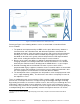
Figure 4: LTE Network Architecture block diagram
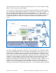
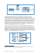
The FH bandwidth utilization has been increasing with the cell capacity. The required
bandwidth, now and in the future, brings forth complexity and costly solutions. Figure 5
illustrates network element partitioning options for the RAN to help mitigate this increase in FH
capacity requirements. In the variation labelled (a), the classical functionality is shown in which
the bulk of the software stack is implemented by the BBU. Progressing to option (b), the PHY
layer is split into upper-PHY and lower-PHY partitions, where lower-PHY is moved to the RRH,
allowing the data stream to traverse the FH before it is transformed for radio consumption,
alleviating some of the bandwidth required. Finally, in option (c), where the BBU is split into a
Distributed Unit (DU) and a Centralized Unit (CU), the architecture has evolved to move even
more of the functionality toward the edge closer to the antennas.
The benefits of a RAN split architecture are to support flexible SW & HW implementations to
allow for scalable and cost-effective solutions. The choice of which functional split to select
depends on deployment scenario, target services, and availability of transport network. The FH
split provides a reduction in the required FH bandwidth, as well as a relaxation in the latency
requirements. The functional split shown is also referred to as Option 7.2.
ii
A motivation for this
approach is to provide the ability to separate functions that scale with user data rates from those
functions that scale with RF bandwidth and number of antennas.
Figure 5: Front Haul split options for the LTE Network.
ii
3GPP defines many functional splits with various advantages and disadvantages. The 7.2 split entails a split
between the “high PHY” and “low PHY” between the BBU and RRH.
PHY
MAC
RLC
PDCP
Etc.
RF
MIMO
(BF)
RRH
DFE,
ET,
DPD
DAC
/
ADC
MME
S-GW
P-GW
HSS
PCRF
eNB
ePC
BBU
SGi
S1-MME
S1-U
S5
Gx
S6a
...
FH
BH
P
H
Y
M
A
C
R
L
C
P
D
C
P
R
R
C
RRH
BBU
...
ePC
P
H
Y
M
A
C
R
L
C
P
D
C
P
R
R
C
...
P
H
Y
M
A
C
R
L
C
P
D
C
P
R
R
C
...
RF
ADC/DAC
DFE
RF
ADC/DAC
DFE
P
H
Y
P
H
Y
RF
ADC/DAC
DFE
FH
DU CU
.
.
.
SGi
S1
S1
S1
a)
b)
c)