Reference Guide NVMe and I/O Topologies for Dell EMC PowerEdge Servers Version: 1.4 Issue Date: 4/22/2020 Abstract This reference guide has been published to educate readers of the unique NVMe and I/O interconnect topologies spanning the PowerEdge rack server portfolio. Customers and solution architects may use this topology information to optimize their workload performance. Additionally, the value propositions and associated trade-offs for selecting certain NVMe configurations are discussed.
Revisions Date Description 10/31/2019 Initial release for 2017/2018 Intel & AMD servers 4/22/2020 Updated to include 2019 AMD servers Acknowledgements This paper was produced by the following people: Name Title Matt Ogle Technical Product Marketing, Dell EMC Corey Hartman System Concept Architect, Dell EMC This paper would not have been possible without help from the following people: Name Title Carol Pflueger Product Management, Dell EMC Neil Klosterman Product Management, Dell EMC Andrew
Contents 1. Introduction....................................................................................................... 4 2. Intel Platforms ................................................................................................... 5 2.1 PowerEdge R440 ................................................................................................ 5 2.2 PowerEdge R640 ................................................................................................ 6 2.3 PowerEdge R740xd ....
1. Introduction Server users considering Non-Volatile Memory Express (NVMe) storage drives seek top-of-the-line performance. The PCIe interface will improve the data delivery path and simplify the software stack, resulting in significant latency reduction and bandwidth increases for storage data transfer transactions. PowerEdge rack servers have unique configurations that are designed for specific value propositions, such as bandwidth, capacity or I/O availability.
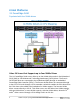
2. Intel Platforms 2.1 PowerEdge R440 Populated with four NVMe drives Figure 1: PowerEdge R440 CPU mapping with four NVMe drives Value 1U Server that Supports up to Four NVMe Drives The 1U PowerEdge R440 server offers up to four NVMe drives and six Serial-Attached SCSI (SAS) or Serial Advanced Technology Attachment (SATA) drives. The first six SATA/SAS drives are connected to the motherboard (MB) through an embedded PowerEdge Raid Controller (PERC).
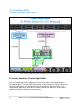
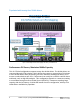
2.2 PowerEdge R640 Populated with eight NVMe drives Figure 2: PowerEdge R640 CPU mapping with eight NVMe drives and two SAS drives 1U Server; Maximize I/O with Eight NVMe This 1U PowerEdge R640 configuration offers up to eight NVMe drives and two SAS/SATA drives. The first eight NVMe drives connect directly to CPU2 and the last two SATA/SAS drives are connected to CPU1 through the MB mini-PERC.
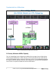
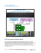
Populated with ten NVMe drives Figure 3: PowerEdge R640 CPU mapping with ten NVMe drives 1U Server; Maximize NVMe Capacity This 1U PowerEdge R640 configuration enables all ten storage slots to NVMe drives. The first eight NVMe drives connect directly to CPU2, while the last two NVMe drives use a PCIe extender card to connect to PCIe slot 1, CPU1.
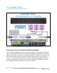
2.3 PowerEdge R740xd Populated with twelve NVMe drives Figure 4: PowerEdge R740xd CPU mapping with twelve NVMe drives and twelve SAS drives Performance 2U Server; Maximize NVMe Bandwidth This 2U R740xd configuration offers up to twelve NVMe drives and twelve SATA/SAS drives. The SATA/SAS drives connect to CPU1 through the integrated PERC, while the twelve NVMe drives map to both CPU1/CPU2 through a direct CPU x4 connection.
Populated with twenty-four NVMe drives Figure 5: PowerEdge R740xd CPU mapping with twenty-four NVMe drives Performance 2U Server; Maximize NVMe Capacity This 2U R740xd configuration supports twenty-four NVMe drives. The NVMe drives are connected through PCIe switches, which allows the system to overprovision PCIe lanes to more NVMe drives while persevering I/O slots, therefore enabling low latency CPU access to twelve devices per CPU.
2.4 PowerEdge R840 Populated with twelve NVMe drives Figure 6: PowerEdge R840 CPU mapping with twelve NVMe drives 4S 2U Server; Maximize NVMe Bandwidth This 2U PowerEdge R840 configuration supports twelve NVMe drives and twelve SATA/SAS drives. The NVMe drives are connected directly to the CPUs and the SATA/SAS drives are connected to the MB PERC.
Populated with sixteen NVMe drives Figure 7: PowerEdge R840 CPU mapping with sixteen NVMe drives 4S 2U Server; Balancing Capacity and Bandwidth This 2U PowerEdge R840 configuration supports sixteen NVMe drives and eight SATA/SAS drives. The NVMe drives are connected to CPU3 and CPU4 through with an extender and the SATA/SAS drives are connected to the PERC through slot 1. This configuration balances NVMe capacity and bandwidth support.
Populated with twenty-four NVMe drives Figure 8: PowerEdge R840 CPU mapping with twenty-four NVMe drives 4S 2U Server; Maximize NVMe Capacity This 2U 4S PowerEdge R840 configuration supports twenty-four NVMe drives. Two PCIe switches are included, which allows the system to overprovision PCIe lanes to more NVMe drives while persevering I/O slots, which are then connected directly to the CPU.
2.5 PowerEdge R940 Populated with twelve NVMe drives on 2S Figure 9: PowerEdge R940 CPU mapping with twelve NVMe drives on 2S CPU 1&2 Mapping 2S or 4S 3U NVMe Configuration This 3U PowerEdge R940 configuration supports twelve NVMe drives and twelve SATA/SAS drives. The NVMe drives are connected directly to CPU1 and CPU2 through I/O slots and the SATA/SAS drives are connected to the MB PERC.
Populated with twelve NVMe drives on 4S Figure 10: PowerEdge R940 CPU mapping with twelve NVMe drives on 4S CPU 3&4 Mapping 4S 3U NVMe Configuration This 3U PowerEdge R940 configuration supports twelve NVMe drives and twelve SATA/SAS drives. The NVMe drives are connected directly to CPU3 and CPU4 through I/O slots and the SATA/SAS drives are connected to the MB PERC. This configuration must be used for an R940 populated w/ 4 sockets.
2.6 PowerEdge R940xa Populated with four NVMe drives Figure 11: PowerEdge R940xa CPU mapping with four NVMe drives Performance 4U Server; Maximize NVMe Capacity This 4U PowerEdge R940xa configuration supports four NVMe drives and twenty SATA/SAS drives. The NVMe drives are connected directly to CPU3 and CPU4 and the SATA/SAS drives are connected to the MB PERC through I/O slot 4. This configuration maximizes NVMe capacity by installing the maximum number of NVMe drives supported by the R940xa.
3. AMD Platforms 3.1 PowerEdge R6515 Populated with ten NVMe drives Figure 12: PowerEdge R6515 CPU mapping with ten NVMe drives 1U Server; Maximize NVMe Performance This 1U PowerEdge R6515 configuration supports ten NVMe drives. All ten of these NVMe drives are directly connected to the CPU. This configuration offers the low latency benefits of NVMe and direct connection to the CPU, without any tradeoffs to the I/O.
3.2 PowerEdge R6525 Populated with ten NVMe drives Figure 13: PowerEdge R6525 CPU mapping with ten NVMe drives 1U Server; Maximize NVMe Performance This 1U PowerEdge R6525 configuration supports ten NVMe drives. All ten of these NVMe drives are directly connected to the CPUs. This configuration offers the low latency benefits of NVMe and direct connection to the CPU, without any tradeoffs to the I/O.
3.3 PowerEdge R7515 Populated with twelve NVMe drives Figure 14: PowerEdge R7515 CPU mapping with twelve NVMe drives and twelve SAS drives 2U 1S Server; Maximize NVMe Bandwidth This 2U PowerEdge R7515 configuration supports twelve NVMe drives and twelve SATA/SAS drives. The NVMe drives are connected directly to the CPU and the SATA/SAS drives are connected to the MB PERC.
Populated with twenty-four NVMe drives Figure 15: PowerEdge R7515 CPU mapping with twenty-four NVMe drives 2U 1S Server; Maximize NVMe Capacity This 2U PowerEdge R7515 configuration supports twenty-four NVMe drives. The NVMe drives are connected directly to the CPUs through two PCIe switches. Customers requiring large capacity with the low latency of NVMe will benefit from this configuration, with up to 24 NVMe drives available for population.
3.4 PowerEdge R7525 Populated with eight NVMe drives Figure 16: PowerEdge R7525 CPU mapping with eight NVMe drives 2U 2S Server; Maximize NVMe Bandwidth This 2U PowerEdge R7525 configuration supports eight NVMe drives and sixteen SATA/SAS drives. The first four NVMe drives are directly connected to CPU2 and the last four NVMe drives are directly connected to CPU1.
Populated with twenty-four NVMe drives Figure 17: PowerEdge R7525 CPU mapping with twenty-four NVMe drives 2U 2S Server; Maximize NVMe Capacity This 2U PowerEdge R7525 configuration supports twenty-four NVMe drives. The first twelve NVMe drives are directly connected to CPU2, while the last twelve NVMe drives are directly connected to CPU1. Customers requiring large capacity with the low latency of NVMe will benefit from this configuration, with up to 24 NVMe drives available for population.
3.5 PowerEdge R6415 Populated with ten NVMe drives Figure 18: PowerEdge R6415 CPU mapping with ten NVMe drives 1U Server; Maximize NVMe Performance This 1U PowerEdge R6415 configuration supports ten NVMe drives. All ten of these NVMe drives are directly connected to the CPU. This configuration offers the low latency benefits of NVMe and direct connection to the CPU, without any tradeoffs to the I/O.
3.6 PowerEdge R7415 Populated with twelve NVMe drives Figure 19: PowerEdge R7415 CPU mapping with twelve NVMe drives and twelve SAS drives 2U 1S Server; Maximize NVMe Bandwidth This 2U PowerEdge R7415 configuration supports twelve NVMe drives and twelve SATA/SAS drives. The NVMe drives are connected directly to the CPU and the SATA/SAS drives are connected to the MB PERC.
Populated with twenty-four NVMe drives Figure 20: PowerEdge R7415 CPU mapping with twenty-four NVMe drives 2U 1S Server; Maximize NVMe Capacity This 2U PowerEdge R7415 configuration supports twenty-four NVMe drives. Two PCIe switches are included, which allows the system to overprovision PCIe lanes to more NVMe drives while persevering I/O slots, which are then connected directly to the CPU.
3.7 PowerEdge R7425 Populated with twelve NVMe drives Figure 21: PowerEdge R7425 CPU mapping with twelve NVMe drives and twelve SAS drives 2U 2S Server; Maximize NVMe Bandwidth This 2U PowerEdge R7425 configuration supports twelve NVMe drives and twelve SATA/SAS drives. Eight of the NVMe drives are connected directly to the CPU and four of the NVMe drives are connected to CPU1 through a PCIe extender card in I/O slot 3.
Populated with twenty-four NVMe drives Figure 22: PowerEdge R7425 CPU mapping with twenty-four NVMe drives 2U 2S Server; Maximize NVMe Capacity This 2U PowerEdge R7425 configuration supports twenty-four NVMe drives. Two PCIe switches are included, which allows the system to overprovision PCIe lanes to more NVMe drives while persevering I/O slots, which are then connected directly to the CPU.
4. Conclusion Each PowerEdge server sub-group has a unique interconnect topology with various NVMe configurations to consider for implementation. To achieve your data center goals with your NVMe investments, it is critical to understand your NVMe topology, as well as why it is the best option from a value prop point of view.