Technical White Paper Setting up BIOS on 15th Generation (15G) Dell EMC PowerEdge Servers Abstract This Dell EMC technical white paper describes the BIOS attributes that you can use to manage and customize your Dell EMC 15G PowerEdge servers. It also defines the fields used in configuring these attributes and best practices for defining values in each field, where appropriate.
Revisions Revisions Date Description March 2018 Initial release by Wei Liu, Mark Shutt, and Paul Rubin July 2018 Added info about the Persistent Memory feature August 2021 Added 15G system setup items Authors Wei Liu — Distinguished Engineer (Dell EMC Server BIOS Engineering) Mark Shutt — Member Technical Staff (Dell EMC Server BIOS Engineering) Honda Wei — Senior Principal Engineer (Dell EMC Server BIOS Engineering) Paul Rubin — Senior Product Manager (Dell EMC Systems Management Marketing) Hyper
Table of contents Table of contents Revisions.............................................................................................................................................................................2 Authors ................................................................................................................................................................................2 Table of contents .......................................................................................
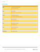
Acronyms Acronyms Acronym ACPI AHCI ASPM BIOS DAPC DBPM DCU Dell EMC iDRAC DPAT ECC GUI I/OAT IMC iSCSI KEK Intel PMEM ME NDC NUMA PERC PK PPI PXE SNC SOL SR-IOV TCG TPM TUI TXT UEFI UPI Prefetch 4 Expanded form Advanced Configuration and Power Interface Advanced Host Controller Interface Advanced State Power Management Basic Input/Output System Dell Active Power Control Demand Based Power Management Data Cache Unit Dell EMC Integrated Dell Remote Access Controller Dell Processor Acceleration Technology
Executive summary Executive summary The 15th generation (15G) of Dell EMC PowerEdge servers provides a System Setup utility to help manage different settings and features of your server without booting to the operating system (OS). Using System Setup, you can configure the System BIOS settings, iDRAC settings, and Device Settings of your server. This technical white paper provides an overview of the usage of System BIOS settings.
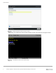
System BIOS Graphical Browser mode of System Setup The TUI (Fig. 2) is enabled when serial console redirection is active. This mode does not support the GUI.
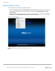
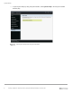
System BIOS Starting System Setup There are multiple ways to start the System Setup utility: • • Press F2 immediately when F2 = System Setup is displayed during system startup, else, press F11 to open the Boot Manager page. You can open System Setup by clicking Boot Manager → Launch System Setup. For iDRAC virtual console users, initiate the System Setup during the next reboot by selecting BIOS Setup option from the Next Boot drop-down menu of the virtual console.
System BIOS • To open System Setup by using Lifecycle Controller, select System Setup in the Lifecycle Controller interface page.
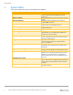
System BIOS 1 System BIOS On the System BIOS Setup page, the following links are displayed: Menu Item System Information Memory Settings Persistent Memory Processor Settings SATA Settings NVMe Settings Boot Settings Network Settings Integrated Devices Serial Communication System Profile Settings System Security Redundant OS Control Miscellaneous Settings 9 Description Read-only. Displays information about the system such as system model name, BIOS version, and Service Tag.
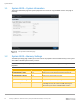
System BIOS 1.1 System BIOS—System Information The System information page lists system properties such as Service Tag and BIOS revision. This page is read-only. The System Information page 1.2 System BIOS—Memory Settings The Memory Settings page enables you to view some of the properties of the installed memory in the system and enable or disable specific memory features. Note: The default option setting is depicted in boldface. Dell EMC reserves the rights to change the default properties.
System BIOS Menu Item System Memory Testing Options • Enabled • Disabled Description Specifies whether the BIOS software-based system memory tests are conducted during POST. When set to Enabled, the memory tests are performed, and test results are displayed on the screen. Note: Enabling results in a longer boot time. The extent of the increase depends on the amount of memory installed in the system.
System BIOS Operating Systems that are NUMA-aware understand the distribution of memory in a particular system and can intelligently allocate memory in an optimal manner. Operating Systems that are not NUMA aware could allocate memory to a processor that is not local resulting in a loss of performance. Die and Socket Interleaving should only be enabled for Operating Systems that are not NUMA aware. Note: This option is only available on systems with AMD processors.
System BIOS Menu Item Correctable Memory ECC SMI Options • Enabled • Disabled Opportunistic Self-Refresh • • Enabled Disabled Description Allows the system to log ECC corrected DRAM errors into the SEL log. Logging these rare errors can help identify marginal components; however, the system will pause for a few milliseconds after an error while the log entry is created. Latency conscious customers may wish to disable the feature. Spare Mode, and Mirror mode require this feature to be enabled.
System BIOS 1.3 System BIOS—Persistent Memory The Persistent Memory page is the main page for saving the Persistent Memory settings. When Intel Optane Persistent Memory is populated, the Intel Persistent Memory page is displayed. If an NVDIMM-N is detected in the system, the NVDIMM-N Persistent Memory page is displayed.
System BIOS 1.3.1 System BIOS—Intel Persistent Memory The Intel Persistent Memory page is the main page for Intel Optane Persistent Memory which displays information about the total persistent memory capacities in the system and the other pages such as Persistent Memory DIMM configuration and Region Configuration.
System BIOS 1.3.2 System BIOS—Persistent Memory DIMM Configuration The Persistent Memory DIMM Configuration page displays a list of Intel Optane DIMMs that are in the system. Persistent Memory DIMM Configuration Menu Item Cryptographic Erase 16 Options • Disabled • Enabled Description Enable or Disable Secure Erase Persistent Memory.
System BIOS 1.3.3 System BIOS—DIMM Information The DIMM Information page displays information about the selected Intel Optane Persistent Memory.
System BIOS Menu Items Persistent Memory DIMM Location Persistent Memory DIMM Capacity Persistent Memory DIMM Speed[MHz] Persistent Memory DIMM Firmware Version Persistent Memory DIMM Serial Number Persistent Memory DIMM Controller revision ID Persistent Memory DIMM Lock state Persistent Memory DIMM Overwrite DIMM status Remain Rate Write Endurance [%] 18 Description The DIMM Slot in which the currently selected Intel Optane Persistent Memory is being populated.
System BIOS 1.3.4 System BIOS—Region Configuration The Region Configuration page displays the persistent memory regions used in the system and for creating goal for Intel Optane Persistent Memory.
System BIOS 1.3.5 System BIOS—Region Information The Region Information page displays information about the selected Region. The page of region Info Menu item Region ID Socket ID Persistent Memory Type Capacity 20 Description Identification number of the currently selected region. Identification number of the CPU socket that the currently selected region is associated with. The persistent memory type that the currently selected region is configured. It can be AppDirect or AppDirect Non-Interleaved.
System BIOS 1.3.6 System BIOS—Create Goal Configuration The Create Goal Configuration page enables an administrator to Create Goal Configuration for the system. Create Goal Configuration Menu Item Operation Target Socket 0-3 Persistent [%]: Memory Mode [%]: 21 Options • Platform • Socket • Disable • Enable • No Change • 0 • 100 Description The region targets to platform level or socket level. Select enable or disable region creation for the selected socket.
System BIOS Note: when Persistent sets to 0%, 100% Memory Mode will be set automatically. When Persistent sets to 100%, Memory Mode will be set to 0%. 1.3.7 System BIOS—NVDIMM-N Persistent Memory The NVDIMM-N Persistent Memory page displays information about the selected NVDIMM-N Persistent Memory.
System BIOS Menu Item NVDIMM Read-Only Options • Disable • Enable NVDIMM Factory Reset and Secure Erase All Dimms • • Disable Enable NVDIMM Interleave • • Disable Enable NVDIMM Factory Reset and Secure Erase • • Disable Enable Description When set to enable, the NVDIMM-N Persistent Memory is set to protected mode. Any write operation to the persistent memory region is not saved. Resets all the NVDIMM-N Persistent Memory in the system to their factory default state and erases all NVDIMM-N Data.
System BIOS 1.4 System BIOS—Processor Settings The Processor Settings page enables you to control the processor-related features. Note: The default option setting is depicted in boldface. Dell EMC reserves the rights to change the default properties. Menu Item Logical Processor CPU Interconnect Speed Options • Enabled • Disabled • Maximum data rate • 11.2 GT/s • 10.4 GT/s • 9.6 GT/s Description Allows you to enable or disable the logical processors (Hyper-Threading Technology).
System BIOS Address Translation Services (ATS) Directory Mode • • Enabled Disabled • • Enabled Disabled Defines the Address Translation Cache (ATC) behavior for devices to cache DMA translations. This field provides an interface to a chipset's Address Translation and Protection Table to translate DMA addresses to host addresses. Defines the Address Translation Cache (ATC) behavior for devices to cache DMA translations.
System BIOS L1 Region Prefetcher • • Enabled Disabled When set to Enabled, the processor provides additional fetch to data along with the data access to the given instruction for performance tuning by controlling the L1 region prefetcher setting. This setting can affect performance based on the application and workloads running on the system. Note: This option is only available on systems with AMD processors.
System BIOS L3 cache as NUMA Domain • • • Enabled Disabled Auto This field specifies that each Core Complex (CCX) within the processor will be declared as a NUMA Domain. Note: This option is only available on systems with AMD processors. Secure Memory Encryption • • Enabled Disabled Enables or disables AMD secure encryption features such as Secure Memory Encryption (SME) and Secure Encrypted Virtualization (SEV).
System BIOS Memory Encryption • Disabled require operating system or hypervisor support. If the operating system supports SME this field does not need to be enabled. If the hypervisor supports SEV this field does not need to be enabled. Enabling TSME affects system memory performance. Note: This option is only available on systems with AMD processors.
System BIOS AVX P1 Dynamic SSTPerformance Profile • • • Normal Level 1 Level 2 AVX P1 level selection • • Enabled Disabled Allows the reconfiguration of the processor via Dynamic or Static SST-PP Select. Note: This option is only available on systems with Intel processors. Note: This option is only available on systems with Intel processors. SSTPerformance Profile • • • Intel SST-BF • • Operating Point 1 | P1: 2.9 GHz, TDP:205w, Core Count:16 Operating Point 2 | P1: 0.
System BIOS Management is set to Maximum Performance and Turbo Boost is Enabled. Note: Additional options such as “Controlled Turbo Limit Minus 1 Bin”, “Controlled Turbo Limit Minus 2 Bins”, and “Controlled Turbo Limit Minus 3 Bins” may be available if a valid DPAT 2.0 (Dell Processor Acceleration Technology 2.0) Enterprise license is installed on the system. • • • • • All 2 3 4 6 Enable number of CCDs (Core Chiplet Die) per Processor.
System BIOS 31 Level 3 Cache N/A Indicates the total size of L3 cache. Number of Cores Maximum Memory Capacity Microcode N/A Indicates the number of cores per processor. N/A Displays the maximum amount of system memory supported by this processor. Indicates the microcode update signature.
System BIOS 1.5 System BIOS—SATA Settings The SATA Settings page is available only on certain servers that support SATA devices. Enables you to change the SATA controller modes and view each port settings. Note: The default option setting is depicted in boldface. Dell EMC reserves the rights to change the defaults. Menu Item Embedded SATA Options • AHCI Mode • RAID Mode • Off Description Enables you to set different modes for the embedded SATA controller(s).
System BIOS 1.6 System BIOS—Boot Settings Boot Settings page enables you to set the boot modes (BIOS vs UEFI) and specify the boot order. Note: The default option setting is depicted in boldface. Dell EMC reserves the rights to change the default properties.
System BIOS 1.7 System BIOS—Network Settings The Network Settings page enables you to modify the UEFI PXE, iSCSI, and HTTP Boot device settings. BIOS will only connect the UEFI drivers and create corresponding boot options for those network devices that have been enabled and configured in this interface. Note: The Network Settings menu is available only in the UEFI boot mode.
System BIOS 1.8 System BIOS—Integrated Devices The Integrated Devices enables you to view and configure the settings of all Integrated Devices in the system. Note: The default option setting is indicating in boldface. Dell EMC reserves the rights to change the default properties. Menu Item User Accessible USB Ports Options • All Ports On • Only Back Ports On • All Ports Off • All Ports Off (Dynamic) Description Configures the User Accessible USB Ports.
System BIOS I/OAT DMA Engine • • Enabled Disabled be configured via the NIC management utilities provided with your system. Allows you to enable or disable the I/O Acceleration Technology (I/OAT) option. I/OAT is a set of DMA features designed to accelerate network traffic and lower CPU utilization. This feature should be enabled only if the hardware and software support I/OAT. Note: This option is only available on systems with Intel processors.
System BIOS Note: This option is only available on systems with AMD processors. This field sets the PCI bus address that preferred IO device resides. Bus address ranges from [0x0:0xFF]. Pcie Preferred IO Bus Value Note: This option is only available on systems with AMD processors.
System BIOS Memory Mapped I/O above 4GB • • Enabled Disabled This field helps in enabling support for PCIe devices that require large amount of MMIO resources. Enable this option only for 64-bit OSs. Note: This option is only available on systems with Intel processors. Memory Mapped I/O Base • • • 56TB 12TB 512GB MMIO base default is 56TB. User should not change the default value unless addressing a known issue. When set to 12TB, the system will map MMIO base to 12TB.
System BIOS slot. Slot disablement must be used only when the installed peripheral card is preventing booting into the OS or causing delays or lockups in system startup. If the slot is disabled, both the Option ROM and UEFI driver are disabled. The card is not enumerated on the PCI bus and won’t be available to the OS. If the Boot Drive is disabled, then the option ROM or UEFI driver from that slot will not run during POST.
System BIOS System BIOS—Serial Communication The Serial Communication page allows you to view and change the properties of the serial communication settings. Note: The default option setting is depicted in boldface. Dell EMC reserves the rights to change the default properties.
System BIOS The following pictures depict the different serial MUX modes for serial communications: External Serial Connector set to Serial Device 1 External Serial Connector set to Serial Device 2 41 Setting up BIOS on 15th Generation (15G) Dell EMC PowerEdge Servers | 508
System BIOS External Serial Connector set to Remote Access Device Note: After console redirection is enabled and active, the BIOS Setup utility interface will operate in text mode (TUI).
System BIOS System BIOS—System Profile Settings The System Profile Settings menu provides various System Profiles to target for performance, performanceper-Watt, or RAS for dense configurations to facilitate different customer workloads. Note: The default option setting is depicted in boldface. Dell EMC reserves the rights to change the default properties.
System BIOS processor power states to achieve Performance/Watt maximized at all utilization levels and workload types while still meeting performance requirements. • • • • • • • • • Maximum Performance 3400MHz 3200MHz 2933MHz 2666MHz 2400MHz 2133MHz 1866MHz • Maximum Reliability Turbo Boost • • Enabled Disabled C1E • • Enabled Disabled Memory Frequency The OS DBPM (Demand Based Power Management) means that it is the OS that controls the processor’s power management.
System BIOS • Memory Refresh Rate • • 1x 2x Uncore Frequency • • Dynamic Maximum When set to Standard mode, the entire memory array will be scrubbed once in a 24-hour period. • When set to Extended mode, the entire memory array will be scrubbed every hour to further increase system reliability. The memory controller will periodically refresh the data in memory. The frequency at which memory is normally refreshed is referred to as 1x refresh rate.
System BIOS Workload Profile • • • • • • • • • CPU Interconnect Bus Link Power Management • • Write Only HPC Profile Low Latency Optimized Profile Virtualization Optimized Performance Profile Virtualization Optimized Performance Per Watt Profile DataBase Optimized Performance Profile Database Optimized Performance Per Watt Profile SDS Optimized Performance Profile SDS Optimized Performance Per Watt Profile Enabled Disabled Allows optimization of performance based on the workload type.
System BIOS Note: This option is only available on systems with Intel processors. Determinism Slider • • Power Determinism Performance Determinism It controls whether BIOS will enable determinism to control performance. Performance - BIOS will enable 100% deterministic performance control. Power BIOS will not enable deterministic performance control. Note: This option is only available on systems with AMD processors.
System BIOS Note: This option is only available on systems with AMD processors. 1.10.1 Intel Platform System Profile System Profile Settings CPU Power Management Memory Frequency Turbo Boost C1E C States Write Data CRC Memory Patrol Scrub Memory Refresh Rate Uncore Frequency Energy Efficient Policy Number of Turbo Boost Enabled Cores for Processor x Monitor/Mwait CPU Interconnect Bus Link Power Management PCI ASPM L1 Link Power Management Processor EIST 1.10.
System BIOS C States Write Data CRC Memory Patrol Scrub Memory Refresh Rate Number of Turbo Boost Enabled Cores for Processor x PCI ASPM L1 Link Power Management Determinism Slider Efficiency Optimized Mode Algorithm Performance Boost Disable (ApbDis) Dynamic Link Width Management (DLWM) Enabled Disabled Standard Disabled Disabled Standard 1x 1x All All Enabled Disabled Power Determinism Disabled Power Determinism Disabled Disabled Disabled Unforced Unforced System BIOS—System Security The Sy
System BIOS Setup password. This option is read-only if the password jumper (PWRD_EN) is not installed in the server. Password Status • • Unlocked Locked Bootmanager Password • • Always Never TPM Security (with TPM 1.2 installed) • • Off On with Pre-boot Measurements On without Pre-boot Measurements • TPM Security (with TPM 2.0 installed) 50 • • Off On TPM Information N/A TPM Firmware TPM Status (TPM 1.2 only) TPM Command (TPM 1.
System BIOS • • • When set to Activate, the TPM will be enabled and activated. When set to Deactivate, the TPM will be disabled and deactivated. When set to Clear, all the contents of the TPM will be cleared. WARNING: Clearing the TPM will cause loss of all the keys in the TPM. This could affect booting to the OS. Note: This field is read-only when TPM Security is set to Off. The action requires an additional reboot before it can become effective.
System BIOS Note: This option is only available on systems with Intel processors. Memory Encryption • • Enabled Disabled Allows enabling or disabling of the Intel Total Memory Encryption Note: This option is only available on systems with Intel processors. Intel(R) SGX • • Off On Allows enabling or disabling of the Intel Software Guard Extension (SGX) Technology. When set to Off, BIOS disables the SGX technology. When set to On, BIOS enables the SGX technology.
System BIOS Note: This option is only available on systems with Intel processors. Select Owner EPOCH input type • • • Enable writes to SGXLEPUBKEYHASH [3..0] from OS/SW • • SGX Owner EPOCH activated Change to New Random Owner EPOCHs Manual User Defined Owner EPOCHs There are two Owner EPOCH modes (Each EPOCH is 64bit): change to new random owner epoch and manually entered by user.
System BIOS • User Defined Delay N/A UEFI Variable Access • • Standard Controlled When set to Immediate, there is no delay for power-up. • When set to Random, the system will create a random delay for power-up. • When set to User Defined, the system will delay power-up by that amount. The system supported user defined power-up delay. This field controls the user-defined AC Recovery Delay. Enter a delay in the range of 60s to 240s. In the future, this may increase to 600 seconds (10 minutes).
System BIOS • • UEFI drivers and executables from mass storage devices Operating System boot loaders Note: Secure Boot is not available unless the Boot Mode (in the Boot Settings menu) is UEFI. Note: Secure Boot is not available unless the “Load Legacy Video Option ROM” setting (in the Miscellaneous Settings menu) is disabled. Secure Boot Policy • • Standard Custom Note: A Setup password is recommended to be enabled for Secure Boot.
System BIOS 56 Secure Boot Policy Summary N/A Secure Boot Custom Policy Settings N/A the hashes are added, the field automatically reverts to Disabled. Note: This field is read-only unless Secure Boot is Enabled, and Secure Boot Policy is Custom. This field is available only in secure system management consoles. View the list of certificates and hashes that Secure Boot uses to authenticate images.
System BIOS System BIOS—Redundant OS Control The Redundant OS Control page allows you to configure the Redundant OS feature, which allows installing an OS on a specified drive, and then hiding that drive until required. Note: The default option setting is depicted in boldface. Dell EMC reserves the rights to change the default properties.
System BIOS System BIOS—Miscellaneous Settings The Miscellaneous Settings page allows you to perform specific functions like updating the asset tag and changing system date and time. Note: The default option setting is depicted in boldface. Dell EMC reserves the rights to change the default properties. Menu Item System Time System Date Asset Tag Options N/A N/A N/A Keyboard NumLock • • On Off F1/F2 Prompt on Error • • Enabled Disabled Description Enables you to set the time on the system.
System BIOS Conclusion Dell EMC provides its customers with products that simplify and streamline their IT processes, freeing administrator’s time to focus on activities that help grow the business. The PowerEdge System Setup utility is one such capability, speeding the configuration of BIOS, iDRAC, and device settings of your servers.
System BIOS A Technical support and resources • • 60 Dell.com/support is focused on meeting customer needs with proven services and support. Dell TechCenter is an online technical community where IT professionals have access to numerous resources for Dell EMC software, hardware and services.