Dell™ OptiPlex™ GX200 Service Manual Small Form-Factor Chassis — Removing and Replacing Parts Low-Profile Chassis — Removing and Replacing Parts Midsize Chassis — Removing and Replacing Parts Mini Tower Chassis — Removing and Replacing Parts Notes, Notices, and Cautions Throughout this guide, blocks of text may be accompanied by an icon and printed in bold type or in italic type.
Back to Contents Page Low-Profile Chassis — Removing and Replacing Parts: Dell™ OptiPlex™ GX200 Systems Service Manual Overview System Power Supply Recommended Tools Expansion-Card Cage Precautionary Measures Riser Boards Internal Views System Board Components Computer Cover Expansion Cards Eject, Power, and Reset Buttons Memory Front-Panel Inserts Microprocessor/Cooling Fan/Heat Sink Assembly Control Panel System Battery Chassis Intrusion Switch System Board Drives Overview This section
possible damage to the system board. 4. Wear a wrist grounding strap, and clip it to an unpainted metal surface, such as the padlock loop on the back of the chassis. If a wrist grounding strap is not available, touch any unpainted metal surface on the back of the computer or on the computer chassis, such as the power supply, to discharge any static charge from your body before touching anything inside the computer.
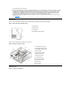
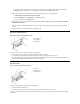
To remove the low-profile chassis computer cover, perform the following steps: 1. Press in on the two securing buttons until the cover is free to swing up (see Figure 3). 2. Raise the back of the cover, and pivot it toward the front of the computer. 3. Lift the cover off the hooks at the front of the chassis. 4. Disengage the tabs that secure the cover to the top of the chassis, and lift the cover away. Figure 4.
NOTE: If the system does not have an audio expansion card but does have an integrated audio controller, be sure that the Sound setting is On. If the system has an audio expansion card, be sure that the Sound setting is Off. 5. While in System Setup, perform the following steps to configure the system if it has an LS-120 SuperDisk drive: a. Set Diskette Drive A and Diskette Drive B to Not Installed. b. Set Secondary Drive 0 or Secondary Drive 1, as appropriate, to Auto. c.
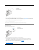
Control Panel Figure 7. Control Panel Removal 1 Control panel 2 Chassis intrusion switch To remove the control panel in the low-profile chassis, perform the following steps: 1. Disconnect the control panel cable from the PANEL connector on the system board (see "System Board Labels" for the location of the PANEL connector). 2. From inside the chassis, remove the mounting screw that secures the control panel to the chassis. 3. Disconnect the chassis intrusion switch cable connector from the control panel.
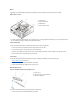
Drives NOTE: In all of the following procedures, left and right refer to your left and right as you face the front of the computer. Figure 9. Drive Locations 1 5.25-inch drive 2 3.5-inch diskette drive 3 Hard-disk drive 4 Chassis intrusion switch NOTE: Computer configurations differ. Your computer may have an Iomega Zip drive installed instead of a 3.5-inch diskette drive, or your computer may have no externally accessible drives installed. 3.5-Inch Diskette Drive To remove the 3.
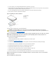
2. Loosen the captive screw securing the hard-disk drive/bracket to the bottom of the chassis. 3. Grasp the drive/bracket, and pivot it upward from the chassis until the two hinge tabs (located on the side opposite the screw) clear the floor divider (see Figure 10). Then lift the bracket upward and out of the chassis. 4. To remove the hard-disk drive from the bracket, place the drive/bracket on a flat surface with the bracket facing up. 5. Remove the four screws that secure the bracket to the drive.
1 Power cable 2 EIDE interface cable 3 IDE1 connector on system board NOTICE: You must attach the blue connector on the EIDE interface cable to the IDE1 connector on the system board to avoid possible damage to your system. 10. If it is not already connected, connect the blue connector on the EIDE interface cable to the IDE1 connector on the system board. To locate the IDE1 connector on the system board, see "System Board Components." 11. Replace the computer cover. 12.
Note the routing of the DC power cables underneath the tabs in the chassis as you remove them from the system board and drives. It is important to route these cables properly when you replace them to prevent them from being pinched or crimped. 3. Remove the screw below the fan guard on the back of the chassis. 4. Slide the power supply toward the front of the computer approximately 1 inch. 5. Lift the power supply up and out of the chassis. Expansion-Card Cage Figure 14.
1 Auxiliary power indicator LED (AUX_LED) 2 Wakeup On LAN (WOL) connector 3 PCI expansion slot 1 (PCI1) 4 PCI expansion slot 2 (PCI2) 5 PCI expansion slot 3 (PCI3) Figure 16.
2 Line-out connector 3 Microphone connector 4 NIC connector 5 Video connector 6 Serial port 2 connector 7 USB connectors (2) 8 Keyboard (lower) and mouse (upper) connectors 9 Parallel port (upper) and serial port 1 (lower) connectors 10 Microprocessor connector 11 RIMM sockets (2) 12 DC power 1 connector 13 DC power 2 connector 14 Chassis intrusion connector 15 Control panel connector 16 External speaker connector 17 EIDE1 connector 18 EIDE2 connector 19 System board speaker 20 System board jumpers 21 Diske
Table 1. System-Board Jumper Settings Jumper Setting PSWD Description (default) Password features are enabled. (default) Password features are disabled. SAFE (default) Reserved (do not change). BIOS (default) Reserved (do not change). RTCRST (default) Real-time clock reset. Can be used for troubleshooting purposes. jumpered unjumpered System Board Labels Table 2 lists the labels for connectors and sockets on your system board, and it gives a brief description of their functions. Table 2.
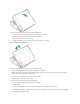
1 8-bit ISA expansion card 2 16-bit ISA expansion card 3 32-bit PCI expansion card Expansion-Card Removal To remove an expansion card, perform the following steps: 1. Remove the computer cover. 2. If necessary, disconnect any cables connected to the card. 3. Remove the screw on the mounting bracket of the card you want to remove. 4. Grasp the card by its outside corners, and ease it out of its connector. 5.
1 Filler bracket 3. Insert the expansion card into the expansion-card connector. If the expansion card is full-length, insert the front end of the card into the corresponding card guide on the inside front of the chassis as you insert the card into its connector. Insert the card's edge connector firmly into the expansion-card slot. 4. When the card is firmly seated in the connector, secure the card's mounting bracket to the chassis with the screw you removed in step 2. 5.
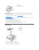
1 Securing clips (2) 2 Notches (2) Microprocessor/Cooling Fan/Heat Sink Assembly Figure 24. Microprocessor/Cooling Fan/Heat Sink Assembly 1 Cooling fan/heat sink assembly 2 ZIF socket 3 Retaining clip CAUTION: The microprocessor/heat sink assembly can get extremely hot. Be sure that the assembly has had sufficient time to cool before you touch it. NOTE: Dell recommends that only a technically knowledgeable person perform this procedure. To replace a microprocessor, perform the following steps: 1.
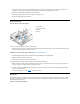
1 Microprocessor package 2 Socket release lever 3 ZIF socket 6. Unpack the new microprocessor package. If any of the pins on the new microprocessor appear to be bent, return the microprocessor package. NOTICE: You must position the microprocessor package correctly in the ZIF socket to avoid permanent damage to the microprocessor and the computer when you turn on the system. 7. Install the microprocessor package in the ZIF socket. a.
1 Battery 2 Socket CAUTION: There is a danger of the new battery exploding if it is incorrectly installed. Replace the battery only with the same or equivalent type recommended by the manufacturer. Discard used batteries according to the manufacturer’s instructions. To remove the system battery, perform the following steps: 1. If possible, enter System Setup and print the System Setup screens. 2.
4. Push evenly on both sides of the system board as you slide and lock it into position (do not twist the system board). 5. Reconnect all cables to the system board. 6. Replace the 5.25-inch drive. 7. Replace the expansion-card cage. 8. Replace the computer cover. 9. Reset the chassis intrusion detector. While in System Setup, confirm that the system data area correctly identifies the type of microprocessor installed.
Back to Contents Page Midsize Chassis — Removing and Replacing Parts: Dell™ OptiPlex™ GX200 System Service Manual Overview System Power Supply Recommended Tools System Board Components Precautionary Measures Expansion Cards Computer Cover Riser Boards Internal View Memory Front-Panel Inserts Microprocessor/Airflow Shroud/Heat Sink Assembly Expansion-Card Cage System Battery Control Panel System Board Drives Overview This section provides procedures for removing and replacing the components
Riser Boards). Computer Cover Figure 1. Computer Cover Removal 1 Securing buttons (2) To remove the computer cover, perform the following steps: 1. Turn off your computer and peripherals, and observe the caution for your personal safety and protection of the equipment described in "Precautionary Measures." 2. If you have installed a padlock through the padlock ring on the back panel, remove the padlock. 3. Press in on the two securing buttons until the cover is free to swing up (see Figure 1). 4.
2. Restart the system. 3. Enter System Setup. To do this, press when F2=Setup appears in the upper-right corner of the screen. If the operating system begins to load into memory, allow the system to complete the load operation, shut down the system, and try again. 4. Restore the system configuration settings. NOTE: If the system does not have an audio expansion card but does have an integrated audio controller, be sure that the Sound setting is On.
1 5.25-inch front-panel insert 2 Ring tabs (2) 3 Posts (2) To remove a 5.25-inch front-panel insert, perform the following steps: 1. Hold the bezel with the front facing you. 2. From the front of the top cover, use your thumbs to press inward on the insert until it snaps free of the cover. To replace a 5.25-inch front-panel insert, position the two ring-tabs over the posts on the inside of the bay opening, and then press the ring tabs over the posts. Expansion-Card Cage Figure 5.
1 Chassis hooks (2) 2 Mounting screw 3 Control panel 4 Control panel cable To remove the control panel, perform the following steps: 1. Remove the hard-disk drive cage. 2. Disconnect the control panel cable from the PANEL connector on the system board (see Figure 14 or the internal service label for the location of the PANEL connector). 3. Remove the mounting screw holding the control panel to the chassis. 4. Slide the control panel out of the hooks holding it to the chassis.
2. Disconnect the DC power and data cables from the back of the drive. 3. Squeeze the retaining tabs that extend from each side of the drive bracket and slide the bracket out of the bay (see Figure 8). 4. Turn the drive assembly upside down and unscrew the four screws that secure the drive to the bracket (see Figure 9). NOTE: For easier access inside the chassis, you may want to rotate the power supply out of the way temporarily. To install a 5.25-inch drive, perform the 5.
1 "Handle" on bracket 2 Screw securing drive to chassis 4. Slide the drive into the chosen bay of the bracket, orienting it so that the connectors on the back of the drive face the back of the chassis— and the power input connector is closest to the floor of the chassis—when the bracket is reinstalled (see Figure 11). Figure 11. Hard-Disk Drive Insertion 1 Drive bracket 2 Tabs (2) 3 1.6-inch drive 4 Screws (4) 5. Align the four screw holes of the drive and bracket.
1 Interface connector 2 Power input connector on drive 3 Lip 4 Rail 5 IDE1 connector 6 IDE2 connector 7 DC power cable 8 EIDE cable NOTICE: You must match the colored strip on the EIDE cable with pin 1 on the IDE1 connector to avoid possible damage to your system. Pin 1 is indicated by a silk-screened "1" printed on the system board. 3. If it is not already connected, connect the other end of the EIDE cable to the appropriate EIDE interface connector on the system board.
To remove the system power supply, perform the following steps: 1. Rotate the system power supply. 2. Disconnect the power cables from all drives. 3. Remove the power supply cables from the system board. 4. Lift the front of the power supply until it stops. Then rotate the power supply away from the chassis. 5. Lift the power supply out of the chassis.
21 Diskette/tape-drive connector 22 Riser board connector 23 Real-time clock reset (RTCRST) jumper 24 Battery 25 Modem audio connector 26 Fan connector 27 CD audio cable connector System Board Jumpers Figure 15 shows the location of the jumpers on the system board. Table 1 lists the system board jumpers and their settings. Figure 15. System Board Jumpers Jumpers are small blocks on a circuit board with two or more pins emerging from them. Plastic plugs containing a wire fit down over the pins.
CD_IN CD-ROM audio interface connector RIMM_x RIMM socket DSKT Diskette/tape drive interface connector ENET Integrated NIC connector EXT_SPKR External speaker connector FAN Microprocessor fan connector HDLED Hard-disk drive LED connector IDEn EIDE interface connector INTRUDER Chassis intrusion switch connector KYBD Keyboard connector MODEM Modem audio connector MONITOR Video connector MOUSE Mouse connector PANEL Control panel connector PARALLEL Parallel port connector; sometimes
5. Grasp the card by its outside corners, and ease it out of its connector. 6. If you are removing the card permanently, install a metal filler bracket over the empty card-slot opening. NOTE: Installing filler brackets over empty card-slot openings is necessary to maintain Federal Communications Commission (FCC) certification of the system. The brackets also keep dust and dirt out of your computer. 7. Replace the expansion-card cage. 8. Replace the computer cover and reset the chassis intrusion detector.
5. When the card is firmly seated in the connector, secure the card's mounting bracket to the chassis with the screw you removed in step 3. 6. Replace the expansion-card cage. 7. Connect any cables that should be attached to the card. 8. See the documentation for the card for information about the card's cable connections. 9. If you are installing the entry-level OptiPlex sound card, disconnect the internal speaker cable from the system board and reconnect it to the INT SPKR connector on the sound card.
1 Securing clips (2) To reinstall a RIMM, perform the following steps: 1. Locate the plastic securing clips at each end of the socket (see Figure 22). 2. Press the clips outward until they snap open. 3. Press the RIMM straight into the slot running down the center of the socket until the securing tabs snap into place around the ends of the RIMM. 4. Replace the computer cover and reset the chassis intrusion detector. Figure 22.
4. Remove the metal retaining clip that secures the heat sink assembly to the microprocessor package by gently pushing down on the folded part of the retaining clip with a small screwdriver. The retaining clip hooks over the sides of the zero insertion force (ZIF) socket. Figure 24. Heat Sink Assembly Removal 1 Retaining clip 2 Heat sink assembly 3 Microprocessor package 4 ZIF socket 5. Remove the heat sink assembly from the microprocessor package.
securing the microprocessor package. Figure 26. Microprocessor Package Installation 1 Microprocessor 2 ZIF socket 3 Pin-1 (beveled corner) 9. Unpack the heat sink included in the replacement kit. NOTICE: Do not reuse the old heat sink assembly when you replace the microprocessor package. Using the old heat sink assembly can cause the microprocessor to overheat because there is not enough thermal compound between the old heat sink assembly and the microprocessor package. 10. Replace the heat sink assembly.
1. If possible, enter System Setup and print the System Setup screens. 2. Remove the computer cover. 3. Remove the system battery by carefully prying it out of its socket with your fingers or with a blunt, nonconducting object such as a plastic screwdriver. When you replace the system battery, orient the new battery with the "+" facing up. Insert the battery into its socket and snap it into place. 4. Replace the computer cover and reset the chassis intrusion detector. System Board Figure 28.
7. Reinstall all components on the system board by performing steps 2 through 8 of the removal process in reverse. 8. Replace the computer cover. 9. Reset the chassis intrusion detector. While in System Setup, confirm that the system data area correctly identifies the type of microprocessor installed.
Back to Contents Page Mini Tower Chassis — Removing and Replacing Parts: Dell™ OptiPlex™ GX200 Systems Service Manual Overview Drives Recommended Tools System Power Supply Precautionary Measures Expansion-Card Cage Internal Views Riser Boards Computer Cover System Board Components Front Bezel Expansion Cards Eject, Power, and Reset Buttons Memory Front-Panel Inserts Microprocessor/Airflow Shroud/Heat Sink Assembly Control Panel System Battery Chassis Intrusion Switch System Board Overvi
possible damage to the system board. 4. Wear a wrist grounding strap, and clip it to an unpainted metal surface, such as the padlock loop on the back of the chassis. If a wrist grounding strap is not available, touch any unpainted metal surface on the back of the computer or on the computer chassis, such as the power supply, to discharge any static charge from your body before touching anything inside the computer.
To remove the mini tower computer cover, perform the following steps: 1. Face the back of the computer and slide the upper half of the padlock ring to the left to unlock the cover release mechanism (see Figure 3). 2. Face the left side cover and press the release button, located at the bottom-left corner of the front bezel (see Figure 3). 3. Lift the bottom of the cover, allowing it to pivot up toward you. 4. Disengage the tabs that secure the cover to the top of the chassis, and lift the cover away.
5. While in System Setup, perform the following steps to configure the system if it has an LS-120 SuperDisk drive: a. Set Diskette Drive A and Diskette Drive B to Not Installed. b. Set Secondary Drive 0 or Secondary Drive 1, as appropriate, to Auto. c. Go to the second page and set Diskette to Off. 6. While in System Setup, reset the chassis intrusion detector under the System Security tab by changing Chassis Intrusion to Enabled, Enabled-Silent, or Disabled. 7.
1 Diskette eject button 2 Power button 3 Reset button To remove the eject, power, and reset buttons, perform the following steps: 1. Lay the front bezel on a flat work surface, with the back of the bezel facing up. 2. To remove the 3.5-inch diskette eject button, pull gently on the plastic part of the button until it comes free. 3. To remove the power button or the reset button, use a small screwdriver and push in the two or three plastic clips that hold the button to the bezel.
1 Control panel 2 Control panel connector 3 Chassis intrusion cable connector 4 Chassis intrusion switch To remove the control panel, perform the following steps: 1. Disconnect the control panel cable from the control panel connector on the system board (see "System Board Labels" for the location of the PANEL connector). Note the routing of the control panel cable as you remove it from the chassis. 2. Disconnect the the chassis intrusion switch cable connector from the control panel. 3.
1. Remove the control panel from the front panel. 2. Disconnect the chassis intrusion switch cable from the control panel (see Figure 9). Note the routing of the chassis intrusion cable as you remove the cable from the chassis. Chassis hooks may hold the cable in place inside the chassis. 3. Slide the chassis intrusion switch out of its slot on the chassis and carefully remove the switch and its attached cable from the chassis. 4. Install the replacement chassis intrusion switch and cable. 5.
When you replace the 3.5-inch diskette drive, be sure that the two hooks on the right side of the bracket engage the mounting holes in the side of the 3.5-inch diskette drive. 5.25-Inch Drive Figure 12. 5.25-Inch Drive Removal 1 Bracket tabs (2) To remove a 5.25-inch drive from a drive bay, perform the following steps. NOTE: For easier access inside the chassis, you may want to rotate the power supply up until it locks (see Figure 20). 1. Remove the front bezel. 2.
Figure 14. New Drive Insertion 1 5.25-inch drive NOTICE: You must match the colored strip on the cable with pin 1 on the drive's interface connector to avoid possible damage to your system. 8. Connect a DC power cable to the power input connector on the back of the drive (see Figure 15). Figure 15. 5.25-Inch Drive Cables Attachment 1 DC power cable 2 EIDE interface connector (on drive) 9. Connect the appropriate EIDE interface cable to the EIDE interface connector on the back of the drive (see Figure 15).
1 Drive bracket slide rail 2 Chassis hinge slots 3 Hinge tabs 4 Sliding tab 5 Drive bracket To remove a hard-disk drive from the mini tower's internal hard-disk drive bracket, perform the following steps. CAUTION: To avoid the possibility of electric shock, turn off the computer and any peripherals, disconnect them from electrical outlets, and then wait at least 5 seconds before you remove the computer cover. Also, before you remove a drive, see the other precautions in "Precautionary Measures." 1.
CAUTION: To avoid the possibility of electric shock, turn off the computer and any peripherals, disconnect them from electrical outlets, and then wait at least 5 seconds before you remove the computer cover. Also, before you install a drive, see the other precautions in "Precautionary Measures." NOTICE: To avoid possibly damaging the drive by ESD, ground yourself by touching an unpainted metal surface on the back of the computer.
1 Blue interface connector (on EIDE1) 2 Interface cable 3 Power cable 4 Power input connector on drive 5 Interface connector on drive NOTICE: You must match the blue connector on the interface cable to the IDE1 connector on the system board to avoid possible damage to your system. 9. If it is not already connected, connect the blue connector of the EIDE cable to the IDE1 connector on the system board. To locate the IDE1 connector, see "System Board Components." 10. Replace the computer cover.
6. Lower the power supply down and away from the computer. Expansion-Card Cage NOTICE: Use a wrist grounding strap as explained in "Precautionary Measures." To remove the expansion-card cage, perform the following steps: 1. Examine any cables connected to expansion cards through the back-panel openings and disconnect any cables that will not reach to where the cage must be placed upon removal from the chassis. 2. Locate the securing lever (see Figure 21).
1 Auxiliary power indicator (AUX_LED) 2 PCI expansion slot 5 (PCI5) 3 Wake On LAN (WOL) connector 4 PCI expansion slot 1 (PCI1) 5 Auxiliary power connector Figure 23.
1 Line-in connector 2 Line-out connector 3 Microphone connector 4 NIC connector 5 Video connector 6 Serial port 2 connector 7 USB connectors (2) 8 Keyboard (lower) and mouse (upper) connectors 9 Parallel port (upper) and serial port 1 (lower) connectors 10 Microprocessor connector 11 RIMM sockets (2) 12 DC power 1 connector 13 DC power 2 connector 14 Chassis intrusion connector 15 Control panel connector 16 External speaker connector 17 EIDE1 connector 18 EIDE2 connector 19 System board speaker 20 System bo
Jumpers are small blocks on a circuit board with two or more pins emerging from them. Plastic plugs containing a wire fit down over the pins. The wire connects the pins and creates a circuit. NOTICE: Make sure your system is turned off before you change a jumper setting. Otherwise, damage to your system or unpredictable results may occur. To change a jumper setting, pull the plug off its pin(s) and carefully fit it down onto the pin(s) indicated. Table 1.
MONITOR Video connector MOUSE Mouse connector PANEL Control panel connector PARALLEL Parallel port connector; sometimes referred to as LPT1 PCIn* PCI expansion-card connector POWER_1 Main power input connector POWER_2 3.
1 Card-edge connector 2 Expansion card 3 Riser board 4 Expansion-card connector 5 Expansion-card cage CAUTION: Some network cards automatically start up the system when they are connected. To guard against electric shock, be sure to unplug your computer from its electrical outlet before installing any expansion cards. To install an expansion card, perform the following steps: 1. Prepare the expansion card for installation, and remove the computer cover.
Figure 29. RIMM Removal 1 Securing clips (2) To reinstall a RIMM, perform the following steps: 1. Locate the plastic securing clips at each end of the socket (see Figure 30). 2. Press the clips outward until they snap open. 3. Press the RIMM straight into the slot running down the center of the socket until the securing tabs snap into place around the ends of the RIMM. 4. Replace the computer cover and reset the chassis intrusion detector. Figure 30.
1 Airflow shroud hooks (2) 2 Chassis tabs (2) 3 Airflow shroud 4 Release tabs 5 Heat sink assembly 4. Remove the metal retaining clip that secures the heat sink assembly to the microprocessor package by gently pushing down on the folded part of the retaining clip with a small screwdriver. The retaining clip hooks over the sides of the zero insertion force (ZIF) socket. Figure 32. Heat Sink Assembly Removal 1 Retaining clip 2 Heat sink assembly 3 Microprocessor package 4 ZIF socket 5.
7. Unpack the new microprocessor package. If any of the pins on the new microprocessor appear to be bent, return the microprocessor package. NOTICE: You must position the microprocessor package correctly in the ZIF socket to avoid permanent damage to the microprocessor and the computer when you turn on the system. 8. Install the microprocessor package in the ZIF socket. a. If the release lever on the ZIF socket is not all the way out, move it to that position. b.
1 Battery 2 Socket CAUTION: There is a danger of the new battery exploding if it is incorrectly installed. Replace the battery only with the same or equivalent type recommended by the manufacturer. Discard used batteries according to the manufacturer’s instructions. To remove the system battery, perform the following steps: 1. If possible, enter System Setup and print the System Setup screens. 2. Rotate the power supply up until it locks (see Figure 20). 3.
1. Remove the RIMMs and the microprocessor/airflow shroud/heat sink assembly, and install them on the replacement board. 2. Set the jumpers on the new system board so that they are identical to those on the old board, unless you are installing a microprocessor upgrade. 3. Push down near each slot to engage the grounding clip onto its corresponding tab. 4. Push evenly on both sides of the system board as you slide and lock it into position (do not twist the system board). 5.
Back to Contents Page Small Form-Factor Chassis — Removing and Replacing Parts: Dell™ OptiPlex™ GX200 Systems Service Manual Overview System Power Supply Recommended Tools Expansion-Card Cage Precautionary Measures Riser Board Internal Views System Board Components Computer Cover Expansion Cards Eject and Power Buttons Memory Control Panel Microprocessor/Cooling Fan/Heat Sink Assembly Chassis Intrusion Switch System Battery Drives System Board Overview This section provides procedures for
possible damage to the system board. 4. Wear a wrist grounding strap, and clip it to an unpainted metal surface, such as the padlock loop on the back of the chassis. If a wrist grounding strap is not available, touch any unpainted metal surface on the back of the computer or on the computer chassis, such as the power supply, to discharge any static charge from your body before touching anything inside the computer.
1 Padlock ring 2 Securing buttons (2) To remove the computer cover, perform the following steps: 1. Press in to retract the padlock ring into the cover to open (see Figure 3). 2. Press in on the two securing buttons until the cover is free to swing up (see Figure 3). 3. Raise the back of the cover, and pivot it toward the front of the computer. 4. Lift the cover off the hooks at the front of the chassis. 5. Disengage the tabs that secure the cover to the top of the chassis, and lift the cover away.
NOTE: If the system does not have an audio expansion card but does have an integrated audio controller, be sure that the Sound setting is On. If the system has an audio expansion card, be sure that the Sound setting is Off. 5. While in System Setup, perform the following steps to configure the system if it has an LS-120 SuperDisk drive: a. Set Diskette Drive A and Diskette Drive B to Not Installed. b. Set Secondary Drive 0 or Secondary Drive 1, as appropriate, to Auto. c.
3. Disconnect the control panel cable from the control panel connector on the system board (see "System Board Labels" for the location of the PANEL connector). Note the routing of the control panel cable as you remove it from the chassis. 4. Remove the mounting screw that secures the control panel to the chassis. 5. Disconnect the chassis intrusion switch cable connector from the control panel. 6. Remove the control panel cable. 7. Remove the control panel from the chassis.
1 Chassis intrusion switch 2 CD-ROM drive 3 3.5-inch diskette drive 4 Hard-disk drive Preliminary Steps You must remove the drive shelf before removing the 3.5-inch diskette drive, the CD-ROM drive, the hard-disk drive, the control panel, the chassis intrusion switch, or the power supply. Figure 9. Drive Shelf Removal 1 Drive shelf 2 Release tabs (2) To remove the drive shelf from the chassis, perform the following steps: 1.
1. If you are replacing a hard-disk drive that contains data you want to keep, make a backup copy of your files before you continue this procedure. 2. Remove the computer cover if not already removed. 3. Remove the drive shelf. 4. Squeeze the tabs on each side of the hard-disk drive/bracket, and pull the hard-disk drive/bracket forward about one inch (see Figure 10). 5. Disconnect the power and interface cables from the back of the drive. 6. Lift the hard-disk drive/bracket away from the chassis. 7.
3. If not already done, remove the drive bracket from the chassis. 4. Attach the new hard-disk drive to the bracket with the four screws you removed in step 8 of the previous procedure. 5. Reinstall the hard-disk drive/bracket in the chassis (see Figure 12). 6. Place the bracket so that the release tabs extend about one inch past the front of the chassis, and align the tabs on the bottom of the bracket with the hooks on the chassis floor. 7.
1. Press down on the release latch on the top left side of the 3.5-inch diskette drive. The 3.5-inch diskette drive will pop up slightly when the latch disengages. 2. Pivot the 3.5-inch diskette drive up and out of the drive shelf. To replace the 3.5-inch diskette drive, perform the following steps: 1. Rotate the replacement drive into position under the right diskette drive bracket on the drive shelf. 2.
1 Interface cable 2 Power cable 3 Power input connector 4 Interface connector Check all cable connections. Fold cables out of the way to provide airflow for the fan and cooling vents. 3. Replace the computer cover; reconnect your computer and peripherals to their electrical outlets, and turn them on. 4. Enter System Setup to update your system configuration information. Set the Drive 1 option under Drives: Primary to Auto. See the online System User's Guide for more information. 5.
1 Securing lever 2 Expansion-card cage 3 Tabs (2) 4 Hooks (2) To remove the expansion-card cage from the chassis, perform the following steps: 1. Remove the computer cover. NOTICE: Use a wrist grounding strap as explained in "Precautionary Measures." 2. Examine the cables connected to expansion cards through the back-panel openings, and disconnect any cables that will not reach to where the cage must be placed when it is removed from the chassis. 3.
1 Line-in connector 2 Line-out connector 3 Microphone connector 4 NIC connector 5 Video connector 6 Serial port 2 connector 7 USB connectors (2) 8 Keyboard (lower) and mouse (upper) connectors 9 Parallel port (upper) and serial port 1 (lower) connectors 10 Microprocessor connector 11 RIMM sockets (2) 12 DC power 1 connector 13 DC power 2 connector 14 Chassis intrusion connector 15 Control panel connector 16 External speaker connector 17 EIDE1 connector 18 EIDE2 connector 19 System board speaker 20 System bo
Jumpers are small blocks on a circuit board with two or more pins emerging from them. Plastic plugs containing a wire fit down over the pins. The wire connects the pins and creates a circuit. NOTICE: Make sure your system is turned off before you change a jumper setting. Otherwise, damage to your system or unpredictable results may occur. To change a jumper setting, pull the plug off its pin(s) and carefully fit it down onto the pin(s) indicated. Table 1.
MOUSE Mouse connector PANEL Control panel connector PARALLEL Parallel port connector; sometimes referred to as LPT1 PCIn* PCI expansion-card connector POWER_1 Main power input connector POWER_2 3.3-V power input connector RISER Riser board connector SERIALn Serial port connector SLOT1_PRI Primary microprocessor connector USB USB connectors Expansion Cards The small form-factor GX200 chassis can accommodate up to two half-length 32-bit PCI expansion cards.
1 Expansion card 2 Card-edge connector 3 Riser board 4 Expansion-card connector 5 Expansion-card cage CAUTION: Some network cards automatically start up the system when they are connected. To guard against electric shock, be sure to unplug your computer from its electrical outlet before installing any expansion cards. To install an expansion card, perform the following steps: 1. Prepare the expansion card for installation, and remove the computer cover.
1 Securing clips (2) To reinstall a RIMM, perform the following steps: 1. Locate the plastic securing clips at each end of the socket (see Figure 26). 2. Press the clips outward until they snap open. 3. Press the RIMM straight into the slot running down the center of the socket until the securing tabs snap into place around the ends of the RIMM. 4. Replace the computer cover. 5. Reset the chassis intrusion detector. Figure 26. RIMM Installation 1 Securing clips (2) 2 Notches (2) 6.
1. Remove the computer cover. 2. Disconnect the cooling fan power cable from its system board connector. 3. Remove the metal retaining clip that secures the cooling fan/heat sink assembly to the microprocessor package by gently pushing down on the folded part of the retaining clip with a small screwdriver. The retaining clip hooks over the sides of the zero insertion force (ZIF) socket. 4. Remove the heat sink assembly from the microprocessor package.
NOTICE: Do not reuse the old heat sink assembly when you replace the microprocessor package. Using the old heat sink assembly can cause the microprocessor to overheat because there is not enough thermal compound between the old heat sink assembly and the microprocessor package. 9. Replace the heat sink assembly. a. Peel the release liner from the adhesive tape attached to the bottom of the new heat sink assembly. b. Place the heat sink assembly on top of the microprocessor package. c.
1 System board 2 Screw To remove the system board, perform the following steps: 1. Disconnect all cables from their connectors at the back of the computer. 2. Remove the drive shelf assembly. 3. Remove the expansion-card cage. 4. Remove the hard-disk drive/bracket. 5. Disconnect all cables from the system board. 6. Remove the screw that secures the system board to the bottom of the chassis (see Figure 31). 7. Slide the system board toward the front of the chassis until it stops. 8.