Dell Latitude E5470 Owner's Manual Regulatory Model: P62G Regulatory Type: P62G001
Notes, cautions, and warnings NOTE: A NOTE indicates important information that helps you make better use of your product. CAUTION: A CAUTION indicates either potential damage to hardware or loss of data and tells you how to avoid the problem. WARNING: A WARNING indicates a potential for property damage, personal injury, or death. © 2017 Dell Inc. or its subsidiaries. All rights reserved. Dell, EMC, and other trademarks are trademarks of Dell Inc. or its subsidiaries.
Contents 1 Working on your computer...............................................................................................6 Safety instructions..............................................................................................................................................................6 Before working inside your computer................................................................................................................................. 6 Turning off your computer.........
Removing the optional finger print reader board...............................................................................................................24 Installing the optional finger print reader board.................................................................................................................25 Removing the LED board.................................................................................................................................................
Communication specifications.......................................................................................................................................... 48 Port and connector specifications.................................................................................................................................... 48 Contactless smart card specifications..............................................................................................................................
1 Working on your computer Safety instructions Use the following safety guidelines to protect your computer from potential damage and to ensure your personal safety. Unless otherwise noted, each procedure included in this document assumes that the following conditions exist: • You have read the safety information that shipped with your computer. • A component can be replaced or, if purchased separately, installed by performing the removal procedure in reverse order.
CAUTION: Before touching anything inside your computer, ground yourself by touching an unpainted metal surface, such as the metal at the back of the computer. While you work, periodically touch an unpainted metal surface to dissipate static electricity, which could harm internal components. CAUTION: Make sure that you place the cooler outlet side of your system at least 5 cm away from wall to prevent system overheat.
Combination Key 83 Keys Keyboard 104 Keys Keyboard + Play or pause a file in Windows Media Player. N/A + Go forward to the next track when playing a file in Windows Media Player. N/A + Print the current desktop screen. + Performs a "Break". This key is used in programming and debugging applications. It has no function in most programs. + Increase the LCD brightness. + Decrease the LCD brightness.
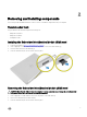
2 Removing and installing components This section provides detailed information on how to remove or install the components from your computer. Recommended tools The procedures in this document require the following tools: • Phillips #0 screwdriver • Phillips #1 screwdriver • Small plastic scribe Installing the Subscriber Identification Module (SIM) card 1. Follow the procedure in Before working inside your computer. 2.
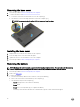
Removing the base cover 1. Follow the procedure in Before working inside your computer. 2. To remove the base cover: a. Loosen the screws that secure the base cover to the computer [1]. b. Lift the base cover from the edge and remove it from the computer [2, 3]. NOTE: You may need a plastic scribe to lift the base cover from the edges. Installing the base cover 1. Align the base cover with the screw holders on the computer. 2. Press the edges of the cover until it clicks into place. 3.
4. Unroute the cable from the routing channel [1] and remove the cable from the battery [2]. Installing the battery NOTE: If your computer supports a 6-cell battery, it will not support a hard drive. 1. Connect the battery cable to the connector on the battery. 2. Route the battery cable through the routing channel on the battery. 3. Insert the battery into the slot on the computer. 4. Tighten the screws to secure the battery to the computer. 5.
Removing the hard drive assembly If the system is shipped with hard drive assembly perform the following steps. 1. Follow the procedure in Before working inside your computer. 2. Remove the: a. base cover b. battery 3. To remove the hard drive assembly: a. Disconnect the hard drive cable from the connector on the system board [1] . b. Remove the screws that secure the hard drive assembly to the computer [2]. c. Lift the hard drive assembly away from the computer [3].
4. Remove the screws that secure the hard drive bracket to the hard drive [1] and lift the hard drive from the hard drive bracket [2]. Installing the hard drive into the hard drive bracket 1. Align the screw holders on the hard drive with the screws on the hard drive bracket. 2. Insert the hard drive into the hard drive bracket. 3. Tighten the screws to secure the hard drive to the hard drive bracket. 4. Install the: a. hard drive assembly b. battery c. base cover 5.
Installing the hard drive assembly If the system is shipped with hard drive assembly perform the following steps. 1. Insert the hard drive assembly into the slot on the computer. 2. Tighten the screws to secure the hard drive assembly to the computer. 3. Connect the hard drive cable to the connector on the hard drive and on the system board. 4. Install the: a. battery b. base cover 5. Follow the procedures in After working inside your system. Installing the optional M.
Installing the optional PCIe SSD If the system is shipped with PCIe SSD perform the following steps. 1. Insert the SSD clip into the slot on the computer. 2. Tighten the screw to secure the SSD clip to the computer. 3. Insert the SSD into the connector on the computer. 4. Place the SSD bracket over the SSD and tighten the screws to secure it to the computer. 5. Install the: a. battery b. base cover 6. Follow the procedure in After working inside your computer.
Installing the memory module 1. Insert the memory module into the memory module socket until the clips secure the memory module. 2. Install the: a. battery b. base cover 3. Follow the procedures in After working inside your computer. Removing the WLAN card 1. Follow the procedure in Before working inside your computer. 2. Remove the: a. base cover b. battery 3. To remove the WLAN card: a. b. c. d. e. Remove the screw that secures the metal bracket to the WLAN card [1].
a. battery b. base cover 6. Follow the procedure in After working inside your system. Removing the WWAN card 1. Follow the procedure in Before working inside your computer. 2. Remove the: a. base cover b. battery 3. To remove the WWAN card: a. b. c. d. Remove the screw that secures the WWAN card [1]. Disconnect the WWAN cables from the connectors on the WWAN card [2]. Unroute the WWAN cables from the routing channel. Remove the WWAN card from the computer [3]. Installing the WWAN card 1.
NOTE: Step 3b is required only if the PCIe SSD card is removed. c. Disconnect the keyboard cables [4, 5]. 4. To remove the dock frame: a. b. c. d. Remove the screw and lift the metal bracket [1,2]. Disconnect the eDP cable [3]. Remove the screws that secure the dock frame to the computer [4]. Lift the dock frame from the computer [5]. Installing the dock frame 1. Place the dock frame on the computer and tighten the screws. 2. Connect the eDP cable. 3. Place the metal bracket and tighten the screw.
Removing the touchpad button 1. Follow the procedure in Before working inside your computer. 2. Remove the: a. base cover b. battery c. dock frame 3. To remove the touchpad button: a. Lift the latch and disconnect the touchpad button cable from the connector [1] [2]. b. Remove the screws that secure the touchpad button [3]. c. Lift and remove the touchpad button away from the computer [4]. Installing the touchpad button 1. Place the touchpad button into the slot on the system board. 2.
b. Lift the metal bracket from the computer [2]. c. Disconnect the power connector port cable from the computer [3]. d. Remove the power connector port from the computer [4]. Installing the power connector port 1. Insert the power connector port into the slot on the computer. 2. Place the metal bracket on the power connector port. 3. Tighten the screw to secure the power connector port to the computer. 4. Route the power connector port cable through the routing channels. 5.
NOTE: The number of keyboard cables may differ based on the computer configuration. 4. To remove the keyboard: a. Using a plastic scribe, lift the keyboard trim from the edges to release it from the keyboard [1, 2, 3]. b. Remove the screws that secure the keyboard to the computer [4]. NOTE: To avoid damage to the keyboard, gently remove the keyboard from the computer. c. Lift the keyboard from computer [5]. Installing the keyboard 1. Align the keyboard with the screw holders on the computer. 2.
Removing the display assembly 1. Follow the procedure in Before working inside your computer. 2. Remove the: a. b. c. d. 3. base cover battery WLAN WWAN To remove the display hinge brackets: a. Remove the screw that secures the display hinge bracket to the computer [1]. b. Remove the display hinge bracket from the computer [2]. c. Remove the screws that secure the display assembly to the computer [3]. 4. 22 To disconnect display cable and remove the display assembly: a. b. c. d. e.
Installing the display assembly 1. Place the display assembly to align with the screw holders on the computer. 2. Tighten the screws to secure the display assembly to the computer. 3. Route the display cable through the routing channel and route the antenna cables by pushing it through the hole. 4. Connect the antenna cables and display cable to the connectors. 5. Place the display cable bracket over the connector and tighten the screw to secure the display cable to the computer. 6.
Installing the optional SmartCard reader board 1. Insert the SmartCard reader board into the slot on the computer. 2. Tighten the screws to secure the SmartCard reader board to the computer. 3. Connect the SmartCard reader cable to the connector on the USH board. 4. Install the: a. b. c. d. e. f. 5. dock frame WWAN card WLAN card hard drive assembly or M.2 SSD or PCIe SSD battery base cover Follow the procedure in After working inside your computer.
Installing the optional finger print reader board 1. Insert the finger print reader board into the slot on the computer. 2. Connect the finger print reader cable to the finger print reader board. 3. Install the: a. b. c. d. e. f. 4. hard drive assembly or M.2 SSD or PCIe SSD dock frame WLAN card WWAN card battery base cover Follow the procedure in After working inside your system. Removing the LED board 1. Follow the procedure in Before working inside your computer. 2. Remove the: a. b. c. d. e.
Installing the LED board 1. Insert the LED board into the slot on the computer. 2. Tighten the screw that secures the LED board to the computer. 3. Connect the LED board cable to the connector on the LED board. 4. Install the: a. b. c. d. e. f. 5. dock frame WWAN card WLAN card hard drive assembly or M.2 SSD or PCIe SSD battery base cover Follow the procedure in After working inside your computer. Removing the heat sink assembly 1. Follow the procedure in Before working inside your computer. 2.
NOTE: The number of screws may vary depending upon the computer configuration. Installing the heat sink assembly 1. Place the heat sink assembly on the system board and align it with the screw holders. 2. Tighten the screws to secure the heat sink assembly to the system board. 3. Connect the fan cable to the connector on the system board. 4. Install the: a. b. c. d. e. f. 5. dock frame WWAN WLAN hard drive assembly or M.
Installing the speakers 1. Place the speakers into the slots on the computer. 2. Route the speaker cable through the retention clips through the routing channel. 3. Connect the speaker cable to the connector on the system board. 4. Install the: a. b. c. d. e. f. 5. dock frame WLAN WWAN hard drive assembly or M.2 SSD or PCIe SSD battery base cover Follow the procedure in After working inside your computer. Removing the system board 1. Follow the procedure in Before working inside your computer.
Installing the system board 1. Align the system board with the screw holders on the computer. 2. Tighten the screws to secure the system board to the computer. 3. Connect the speaker cable to the connector on the system and route the cable through the routing channels. 4. Connect the power connector and coin cell battery cables to the connectors on the system board: 5. Install the: a. b. c. d. e. f. g. h. i. j. k. 6.
b. Lift the coin cell battery to release it from the adhesive and remove it from the system board [2]. Installing the coin cell battery 1. Place the coin cell battery into the slot on the system board. 2. Connect the coin cell battery cable to the connector on the system board. 3. Install the: a. b. c. d. e. f. g. h. i. j. k. l. 4. power connector port WLAN heat sink assembly WWAN dock frame hard drive assembly or M.2 SSD or PCIe SSD keyboard memory module dock frame hard drive assemblyor M.
j. heat sink assembly k. power connector port l. system board 3. The palmrest is the remaining component, after removing all the components. Installing the palmrest 1. Align the palmrest on the computer. 2. Install the: a. b. c. d. e. f. g. h. i. j. k. l. 3. system board power connector port dock frame WLAN heat sink assembly WWAN hard drive assembly or M.2 SSD or PCIe SSD keyboard memory module battery base cover SIM card Follow the procedure in After working inside your computer.
3 System setup options NOTE: Depending on the computer and its installed devices, the items listed in this section may or may not appear. Boot Sequence Boot Sequence allows you to bypass the System Setup–defined boot device order and boot directly to a specific device (for example: optical drive or hard drive). During the Power-on Self Test (POST), when the Dell logo appears.
• Change the system configuration information after you add, change, or remove any hardware in your computer. • Set or change a user-selectable option such as the user password. • Read the current amount of memory or set the type of hard drive installed. Before you use System Setup, it is recommended that you write down the System Setup screen information for future reference. CAUTION: Unless you are an expert computer user, do not change the settings for this program.
System Configuration screen options Option Description Integrated NIC Allows you to configure the integrated network controller. The options are: Parallel Port Serial Port SATA Operation Drives SMART Reporting • Disabled • Enabled • Enabled w/PXE: This option is enabled by default. Allows you to configure the parallel port on the docking station. The options are: • Disabled • AT: This option is enabled by default. • PS2 • ECP Allows you to configure the integrated serial port.
Option Description The options are: USB/Thunderbolt Configuration • Enable USB Boot Support: This option is enabled by default. • Enable External USB Port: This option is enabled by default. This is an optional feature. This field configures the integrated USB controller. If Boot Support is enabled, the system is allowed to boot any type of USB Mass Storage Devices (HDD, memory key, floppy). If USB port is enabled, device attached to this port is enabled and available for OS.
Option Description • 15 minute • Never Keyboard Backlight This feature defines the timeout value for the keyboard backlight when system is running only on battery Timeout on Battery power. Touchscreen • 5 seconds: This option is enabled by default. • 10 seconds • 15 seconds • 30 seconds • 1 minute • 5 minute • 15 minute • Never This option controls to enabled or disabled the touchscreen. NOTE: Touchscreen option is available only if the computer is a touch version.
Option Description Default setting: Not set System Password Allows you to set, change or delete the system password. NOTE: Successful password changes take effect immediately. Default setting: Not set Internal HDD-0 Password Allows you to set, change or delete the system’s internal hard disk’s password. Strong Password Allows you to enforce the option to always set strong passwords. Default setting: Not set Default Setting: Enable Strong Password is not selected.
Option Description NOTE: The Activate and Disable options will permanently activate or disable the feature and no further changes will be allowed Default setting: Deactivate CPU XD Support Allows you to enable the Execute Disable mode of the processor. Enable CPU XD Support (default) OROM Keyboard Access Allows you to set an option to enter the Option ROM Configuration screens using hotkeys during boot.
Intel Software Guard Extensions screen options Option Description Intel SGX Enable This field specifies you to provide a secured environment for running code/storing sensitive information in the context of the main OS. The options are: • Disabled • Enabled Default setting: Disabled Enclave Memory Size This option sets SGX Enclave Reserve Memory Size.
Option Description Default setting: Enabled. Power Management screen options Option Description AC Behavior Allows you to enable or disable the computer from turning on automatically when an AC adapter is connected. Default setting: Wake on AC is not selected. Auto On Time Allows you to set the time at which the computer must turn on automatically.
Option Description Peak Shift This option enables you to minimize the AC power consumption during the peak power times of day. After you enable this option, your system runs only in battery even if the AC is attached. Dock Support on Battery This option allows you to use the docking station when AC power is absent but only when the battery is above a certain charge percentage. The percentage may change per battery and per platform.
Option Description Enable Network. This option is enabled by default. Fn Key Emulation Allows you to set the option where the Scroll Lock key is used to simulate the Fn key feature. Enable Fn Key Emulation (default) Fn Lock Options MEBx Hotkey Allows you to let hot key combinations Fn + Esc toggle the primary behavior of F1–F12, between their standard and secondary functions. If you disable this option, you cannot toggle dynamically the primary behavior of these keys.
Wireless screen options Option Description Wireless Switch Allows to set the wireless devices that can be controlled by the wireless switch. The options are: • WWAN • GPS (on WWAN Module) • WLAN/WiGig • Bluetooth All the options are enabled by default. NOTE: For WLAN and WiGig enable or disable controls are tied together and they cannot be enabled or disabled independently. Wireless Device Enable Allows you to enable or disable the internal wireless devices.
System Log screen options Option Description BIOS Events Allows you to view and clear the System Setup (BIOS) POST events. Thermal Events Allows you to view and clear the System Setup (Thermal) events. Power Events Allows you to view and clear the System Setup (Power) events. Updating the BIOS in Windows It is recommended to update your BIOS (System Setup), on replacing the system board or if an update is available.
NOTE: Your computer is shipped with the system and setup password feature is disabled. Assigning a system password and setup password You can assign a new System Password only when the status is in Not Set. To enter the system setup, press F2 immediately after a power-on or re-boot. 1. In the System BIOS or System Setup screen, select Security and press Enter. The Security screen is displayed. 2. Select System Password and create a password in the Enter the new password field.
4 Technical specifications NOTE: Offerings may vary by region. For more information regarding the configuration of your computer in: • Windows 10, click or tap Start • Windows 8.1 and Windows 8, from the charms sidebar, click or tap Settings → Change PC settings. In the PC Settings window, select PC and devices → PC Info. → Settings → System → About. • Windows 7, click Start , right-click My Computer, and then select Properties.
Feature Specification • dedicated graphics (Intel 6th generation U-type processors) – 1 DIMM slot • dedicated and integrated graphics (Intel 6th generation H-type processors) – 2 DIMM slots Memory capacity 4 GB, 8 GB, and 16 GB Memory type DDR4 SDRAM Speed 2133 MHz Minimum memory 4 GB Maximum memory 32 GB Storage specifications Feature Specification HDD Up to 1 TB SSD 2.5 inches Up to 512 GB SSD M.
Camera specifications Feature Specification Camera resolution 0.
Contactless smart card specifications Feature Specification Supported Smart Cards/Technologies BTO with USH Display specifications Feature Type Specification • Non-touch FHD anti-glare • HD anti-glare Height 205.6 mm (8.09 inches) Width 320.9 mm (12.63 inches) Diagonal 355.
Feature Specification Refresh rate 60 Hz Maximum viewing angles (horizontal) 40/40 Maximum viewing angles (vertical) +10/-30 Pixel pitch 0.2265 mm (0.009 inches) Keyboard specifications Feature Number of keys Specification • United States: 82 keys • United Kingdom: 83 keys • Japan: 86 keys • Brazil: 84 keys Touchpad specifications Feature Specification Active Area: X-axis 99.50 mm Y-axis 53.
Feature Specification Life span 300 discharge per charge cycles Temperature range Operating • Charge: 0°C to 50°C • Discharge: 0°C to 70°C • Operating: 0°C to 35°C (32°F to 95°F) Non-operating - 40°C to 65°C (- 40°F to 149°F) Coin cell battery 3 V CR2032 lithium coin cell AC Adapter specifications Feature Specification Type 65 W Input voltage 100 V AC to 240 V AC Input current (maximum) 1.5 A Input frequency 50 Hz to 60 Hz Output current 3.34 A Rated output voltage 19.5 +/– 1.
Environmental specifications Temperature Specifications Operating 0°C to 35°C (32°F to 95°F) Storage –40°C to 65°C (–40°F to 149°F) Relative humidity Specifications (maximum) Operating 10 % to 90 % (non condensing) Storage 5 % to 95 % (non condensing) Altitude (maximum) Specifications Operating 0 m to 3048 m (0 ft to 10,000 ft) Non-operating 0 m to 10,668 m (0 ft to 35,000 ft) Airborne contaminant level G1 as defined by ISA-71.
5 Diagnostics If you experience a problem with your computer, run the ePSA diagnostics before contacting Dell for technical assistance. The purpose of running diagnostics is to test your computer's hardware without requiring additional equipment or risking data loss. If you are unable to fix the problem yourself, service and support personnel can use the diagnostics results to help you solve the problem.
5. Select the device from the left pane and click Run Tests 6. If there are any issues, error codes are displayed. Note the error code and contact Dell. Device status lights Table 1. Device status lights Icon Name Description Power status light Turns on when you turn on the computer and blinks when the computer is in a power management mode. Battery charge indicator Turns on steadily or blinks to indicate battery charge status.
Battery status lights If the computer is connected to an electrical outlet, the battery light operates as follows: Alternately blinking amber light and white light An unauthenticated or unsupported non-Dell AC adapter is attached to your laptop. Alternately blinking amber light with steady white light Temporary battery failure with AC adapter present. Constantly blinking amber light Fatal battery failure with AC adapter present. Light off Battery in full charge mode with AC adapter present.
6 Contacting Dell NOTE: If you do not have an active Internet connection, you can find contact information on your purchase invoice, packing slip, bill, or Dell product catalog. Dell provides several online and telephone-based support and service options. Availability varies by country and product, and some services may not be available in your area. To contact Dell for sales, technical support, or customer service issues: 1. Go to Dell.com/support. 2. Select your support category. 3.