Dell Lifecycle Controller GUI v2.10.10.
Notes, cautions, and warnings NOTE: A NOTE indicates important information that helps you make better use of your computer. CAUTION: A CAUTION indicates either potential damage to hardware or loss of data and tells you how to avoid the problem. WARNING: A WARNING indicates a potential for property damage, personal injury, or death. Copyright © 2015 Dell Inc. All rights reserved. This product is protected by U.S. and international copyright and intellectual property laws.
Contents 1 Introduction........................................................................................................... 7 Why use Lifecycle Controller?.............................................................................................................. 7 Benefits of using iDRAC with Lifecycle Controller...............................................................................8 What's new in this release?................................................................................
Exporting hardware inventory — current or factory shipped............................................................27 Exporting hardware inventory to a USB drive.............................................................................. 28 Exporting hardware inventory to a network share...................................................................... 28 Viewing or exporting hardware inventory after part replacement...................................................
Removing encryption and deleting data...................................................................................... 55 Breaking mirrored drives.....................................................................................................................55 System setup — Advanced Hardware Configuration.........................................................................55 Modifying device settings..............................................................................................
9 Using the System Setup and boot manager.................................................. 79 Choosing the system boot mode...................................................................................................... 80 Entering System Setup........................................................................................................................80 Responding to error messages.....................................................................................................
Introduction 1 Dell Lifecycle Controller provides advanced embedded systems management to perform systems management tasks such as deploy, configure, update, maintain, and diagnose using a graphical user interface (GUI). It is delivered as part of integrated Dell Remote Access Controller (iDRAC) out-of-band solution and embedded Unified Extensible Firmware Interface (UEFI) applications in the latest Dell servers.
and embedded, formatting or reinstalling the operating system does not remove the tool, thus saving significant time and money. Benefits of using iDRAC with Lifecycle Controller The benefits include: • Increased availability — Early notification of potential or actual failures that help prevent a server failure or reduce recovery time after failure.
Key features The key features of Lifecycle Controller are: • Provisioning — Entire preoperating system configuration from a unified interface. • Deploying — Simplified operating system installation with the embedded drivers on Lifecycle Controller. Unattended installation mode is available for Microsoft Windows and Red Hat Enterprise Linux 7 operating systems. • Download drivers for operating system installation from one of the following sources: – ftp.dell.
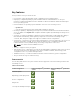
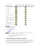
Features Supported Dell PowerEdge 12th generation servers Dell PowerEdge 13th generation servers Server profile import Part replacement Local updates Driver packs Hardware inventory Remote services (through WSMan) Unattended operating system installation — Microsoft Windows Unattended operating system installation — Red Hat Enterprise Linux 7 Deploying an operating system using UEFI Secure Boot Enhanced repurpose or retire server NOTE: Specific component selection is not supported on the Dell's 12th gene
Table 2.
Device ID Indicates the Service Tag of the server on which iDRAC is installed. License • • • • • Entitlement ID — Indicates a unique ID provided by the manufacturer. Status — Indicates the status of the installed license. Description — Indicates the license details. License Type — Indicates the type of license of the device. For example, Evaluation, Evaluation Extension, or Perpetual. Expiration — Indicates the date and time at which the license expires.
• The Owner’s Manual provides information about system features and describes how to troubleshoot the system and install or replace system components. • Lifecycle Controller Web Services Interface Guide–Windows and Linux. Social Media Reference To know more about the product, best practices, and information about Dell solutions and services, you can access the social media platforms such as Dell TechCenter and YouTube.
Dell provides several online and telephone-based support and service options. Availability varies by country and product, and some services may not be available in your area. To contact Dell for sales, technical support, or customer service issues: 1. Go to dell.com/support. 2. Select your support category. 3. Verify your country or region in the Choose a Country/Region drop-down list at the bottom of the page. 4. Select the appropriate service or support link based on your need.
2 Using Lifecycle Controller This section provides information about starting, enabling, and disabling Lifecycle Controller. Before using Lifecycle Controller, make sure that the network and iDRAC are configured. For more information, see the Integrated Dell Remote Access Controller User’s Guide at dell.com/esmmanuals. Starting Lifecycle Controller To start Lifecycle Controller, restart the system and press during POST to select Lifecycle Controller from the list displayed.
Message Lifecycle Controller Update Required Lifecycle Controller not available Cause Resolution • The embedded device that has Enable Lifecycle Controller. For a backup of the product may more information, see Enabling contain corrupted data. Lifecycle Controller. • Ungracefully exits Lifecycle Enable Lifecycle Controller. For Controller for three more information, see Enabling consecutive times if one of the Lifecycle Controller.
4. Under Lifecycle Controller, select Disabled. 5. On the System Setup Main Menu page, select Finish to save the settings. 6. Select Yes to restart the system. Canceling Lifecycle Controller actions If Lifecycle Controller causes the system to restart twice, cancel the Lifecycle Controller actions. However, if Lifecycle Controller causes the system to restart the third time, the message Lifecycle Controller update required is displayed, you must enable Lifecycle Controller.
Configuring network settings for a NIC 1. Start Lifecycle Controller. For more information, see Starting Lifecycle Controller. 2. On the left pane, click Settings. 3. On the Settings page, click Network Settings. 4. From the NIC Card drop-down menu, select the NIC port that you want to configure. NOTE: You can use only one NIC at a time to communicate with the network. 5.
2. Click View Release Notes. Lifecycle Controller features This section provides a brief description about the Lifecycle Controller features and helps you understand how to use the Lifecycle Controller wizards most effectively. Each feature is a wizard in Lifecycle Controller, which supports the following features: • Home — Navigate back to the Home page. • Lifecycle Log — View and export the Lifecycle Controller log, and add a work note to the log.
Operating system deployment 3 The OS Deployment feature allows you to deploy standard and custom operating systems on the managed system. You can also configure RAID before installing the operating system if it is not already configured. Lifecycle Controller allows deploying the operating system using the following options: • Manual installation • Unattended installation. For more information on unattended installation, see Unattended installation. • UEFI Secure Boot.
• • Secure Boot — Allows you to enable or disable the Secure Boot option. Click Enabled to secure the boot process by checking if the drivers are signed with an acceptable digital signature. This option is available only for the UEFI boot mode. For more information on Secure Boot, see UEFI Secure Boot. NOTE: The Secure Boot option is available only if the Load Legacy Video Option ROM setting is set to disabled.
UEFI Secure Boot Unattended installation Post reboot scenarios Using the optional RAID configuration Using the optional RAID configuration When you install an operating system, you can: • Deploy the operating system without configuring RAID. • Configure the hard-disk drives using the optional RAID configuration wizard and deploy the operating system. Alternatively, you can configure RAID through the RAID configuration page from the Hardware Configuration → Configuration Wizards → RAID Configuration.
You can also see the Unattended Installation of Operating Systems from Lifecycle Controller on Dell PowerEdge Servers white paper at Dell TechCenter. NOTE: The unattended installation feature is supported only for Microsoft Windows and Red Hat Enterprise Linux 7 operating systems. If you select an operating system other than Windows or Red Hat Enterprise Linux 7, the Unattended Install option is grayed out.
Driver access Lifecycle Controller provides a local repository for drivers that are required for installing the operating system. Based on the operating system you want to install, the OS Deployment wizard extracts these drivers and copies them to a temporary directory (OEMDRV) on the managed system. These files are deleted after 18 hours or when you: • Refresh the AC power cycle, which resets the iDRAC.
Using the optional RAID configuration 25
Monitor 4 Using Lifecycle Controller, you can monitor the hardware inventory and events of a server throughout its life cycle.
For more information about the easy-to-use names of the hardware components, see Easy-to-use System Component Names. NOTE: View and export factory-shipped inventory feature is grayed out if the Repurpose or Retire System option is selected, which permanently deletes the factory-shipped inventory.
3. In the right pane, click Hardware Inventory. 4. Click Export Current Inventory or Export Factory Shipped Hardware Inventory. 5. If you are exporting the inventory to a local USB drive, select USB Drive. If you are exporting the file to a shared folder on a network, select Network Share. For more information, see Exporting Hardware Inventory To A USB Drive or Exporting Hardware Inventory To A Network Share.
• Share Name — Type the server IP or host name followed by the root of the network share. Examples: \\192.168.0.120\sharename or \\hostname\sharename. • Domain and User Name — Type the domain and user name required to log on to the network share. For example, loginname@myDomain or domain\user name. If there is no domain, type the user name. • Password — Type the correct password. • File Path — Type the sub-directories, if any. For example, 2011\Nov.
Viewing or exporting current inventory after resetting Lifecycle Controller NOTE: The system automatically turns off after you select the Repurpose or Retire System option. To view or export the current hardware inventory data after resetting Lifecycle Controller: 1. Turn on the system and wait for a few minutes for iDRAC to start functioning. 2.
You can use the filtering and sorting options to view the Lifecycle Log. NOTE: As the system events are generated by various systems management tools, you may not view the events in log immediately after they were logged. To view the Lifecycle Log history and use the filtering options: 1. Start Lifecycle Controller. For more information, see Starting Lifecycle Controller. 2. In the left pane, click Lifecycle Log. 3. In the right pane, click View Lifecycle Log History.
To export the Lifecycle Log: 1. Start Lifecycle Controller. For more information, see Starting Lifecycle Controller. 2. In the left pane, click Lifecycle Log. 3. In the right pane, click Export Lifecycle Log. 4. Select either USB Drive or Network Share. For more information, see Exporting Lifecycle Log To A USB Drive or Exporting Lifecycle Log To A Network Share.
NOTE: The following characters are supported for user name and password: – Digits (0–9) – Alphabets (a-z, A-Z) – Hyphen (-) NOTE: Lifecycle Controller allows 256 characters in a path that includes the file name and file extension. For example, if 56 characters are used for file name and extension, only 200 characters can be used for the path. Lifecycle Controller does not support these characters -:, *,?,”,<,>,|,#,%,^, and SPACE.
5 Firmware update Using Lifecycle Controller, the system can be updated using the repositories accessible through FTP or on a locally attached USB drive, DVD, or network share. Use the Firmware Update page to: • View the current version of the installed applications and firmwares. • View a list of available updates. • Select the required updates, downloads (automatic), and then apply the updates to the following components listed in the table.
Component Name Firmware Rollback Out-of-band — Supported? (Yes or System Restart No) Required? In-band — System Restart Required? Lifecycle Controller GUI — Restart Required? CMC (on PowerEdge FX2 servers) No Yes Yes Yes OS Collector No No No No PowerEdge servers only) * Indicates that though a system restart is not required, iDRAC must be restarted to apply the updates. iDRAC communication and monitoring will temporarily be interrupted.
Version compatibility The version compatibility feature enables you to update the component firmware versions that are compatible with system components. In case of compatibility issues, Lifecycle Controller displays upgrade or downgrade error messages during the update. Updating firmware You can update to the latest version of Lifecycle Controller using the Firmware Update wizard. It is recommended that you run the Firmware Update wizard regularly to access the latest updates.
7. Select the components that require an update, and then click Apply. The update process is initiated and the firmware update is completed. After restart, the system is ready to use. NOTE: The system does not restart if operating system driver packs, OS collector tool, or hardware diagnostics are updated. NOTE: When applying more than one update, the system may restart between updates. In this case, Lifecycle Controller restarts the server and automatically continues the update process.
To access the repository on the local drive, create a repository on a DVD or USB drive and attach it to the server locally or using a virtual media. Using a DVD Use either the Server Update Utility (SUU) DVDs or custom DVDs (SUU ISO downloaded from dell.com/ support and written to a DVD) to perform the firmware updates. The available DVDs are: • OpenManage SUU DVD to update all the server components such as Lifecycle Controller, Dell Diagnostics, BIOS, RAID controller, NIC, iDRAC, and Power Supply Unit.
NOTE: If the catalog file is located in a root folder, do not enter the file name in the File Path or Update package path field. However, if the catalog file is located in a subdirectory, enter the subdirectory name. NOTE: If the catalog file or DUP is downloaded from ftp.dell.com, do not copy them to a subdirectory. NOTE: Lifecycle Controller allows 256 characters in a path that includes the file name and file extension.
NOTE: Lifecycle Controller allows 256 characters in a path that includes the file name and file extension. For example, if 56 characters are used for file name and extension, only 200 characters can be used for the path. Lifecycle Controller does not support these characters -:, *,?,”,<,>,|,#,%,^, and SPACE. Using a proxy FTP server Using Lifecycle Controller, you can update the firmware by using ftp.dell.
CIFS For CIFS, type the following details: • Share Name — Path to the shared folder where the DUPs or repository is located. For example, \ \192.168.20.26\sharename or \\servername\sharename. • Domain and User Name — Type the correct domain and user name required to log on to the network share. For example, login-name@myDomain, and if there is no domain, type only the login name. For example, login-name. • Password — Password to access the share.
Release Date: YYYY-MM-DD Source: USB Drive or CD or DVD (): \. By default, Lifecycle Controller selects the components for which the current updates are available. 2. Click Apply. The system may restart after the update process is complete. When applying more than one update, the system may restart between the updates and launch back to Lifecycle Controller, and continue with the other selected updates.
NOTE: If you update any firmware only once, the rollback feature provides the option to revert to the factory-installed component firmware image. If you update the firmware more than once, the factory‑installed images are overwritten and you cannot revert to them. To roll back a firmware: 1. Start Lifecycle Controller. For more information, see Starting Lifecycle Controller. 2. In the left pane, click Firmware Update. 3. In the right pane, click Launch Firmware Rollback.
Configure 6 Lifecycle Controller provides various system configuration wizards. Use the configuration wizards to configure system devices. The Configuration Wizards has: • System Configuration Wizards — This wizard includes LCD Panel Security, iDRAC Settings, System Date and Time Configuration, and vFlash SD card Configuration. • Storage Configuration Wizards — This wizard includes RAID Configuration, Key Encryption, and Break Mirror.
• 6. View Only • Disable Click Finish to apply the changes. Configuring iDRAC To configure iDRAC parameters applicable to the system, such as LAN, common IP settings, IPv4, IPv6, Virtual Media, and LAN user configuration use the iDRAC Settings wizard. NOTE: You can also use the System Setup utility during startup for configuring iDRAC. For more information about the System Setup utility, see Using The System Setup Program And Boot Manager. To configure and manage the iDRAC parameters: 1.
4. Under System Configuration Wizards, click System Time and Date Configuration. The default system time and system date displayed in Lifecycle Controller is the date and time reported by the system BIOS. 5. Modify the System Time and System Date (HH:MM:SS AM or PM), as required. 6. Click Finish to apply the changes. Configuring vFlash SD card Use the licensed feature to enable or disable the vFlash SD card, check the health and properties, and initialize the vFlash SD card.
3. In the right pane, click Configuration Wizards. 4. On the System Configuration Wizards page, click vFlash SD Card Configuration. The vFlash SD Card page is displayed. 5. Click Initialize vFlash to delete all the data present in the vFlash SD card. NOTE: The Initialize vFlash option is not available after you disable the vFlash SD card.
A foreign configuration is a set of physical disk drives containing a RAID configuration that is introduced to the system, but is not managed by the RAID controller to which it is attached. You may have a foreign configuration if physical disk drives have been moved from one RAID controller to another RAID controller. NOTE: Import Foreign Configuration is supported from System Setup → Advanced Hardware Configuration → Device Settings.
• RAID 6 — Stripes data across the physical disks, and uses two sets of parity information for additional data redundancy. If one or two physical disks fail, the data can be rebuilt using the parity information. RAID 6 offers good data redundancy and read performance but slower write performance. • RAID 10 — Combines mirrored physical disks with data striping. If a physical disk fails, data can be rebuilt using the mirrored data. RAID 10 offers good read and write performance with good data redundancy.
• Encryption Capability — Select Yes to enable encryption capability. • Select Span Length — Select the span length. The span length value refers to the number of physical disk drives included in each span. Span length applies only to RAID 10, RAID 50, and RAID 60. The Select Span Length drop‑down list is active only if you have selected RAID 10, RAID 50, or RAID 60.
• Secure Virtual Disk — Select to secure the virtual drive using the controller’s security key. NOTE: The secure virtual drive is created only if the controller security key is created and the selected disks are Self-Encrypting Drives (SEDs). Viewing summary The Summary page displays the virtual disk attributes based on selections. CAUTION: Clicking Finish deletes all existing virtual drives except any foreign configurations that you specified. All data residing on the virtual drives is lost.
The Virtual Disk Attributes page is displayed. 8. Select the virtual disk parameters and click Next. The Summary page is displayed. 9. To apply the RAID configuration, click Finish. Related Links Selecting a RAID controller Foreign configuration found Selecting RAID levels Selecting physical disks Setting virtual disk attributes Viewing summary Creating a secure virtual disk on a RAID controller Make sure that the controller is encrypted with a local key.
Viewing summary Applying the local key on a RAID controller Key encryption Use the Key Encryption feature to: • Apply local encryption for PERC H710, H710P, H730, H730P, H810, and H830 RAID controllers. • Delete the local encryption key. • Encrypt the existing unsecure virtual drives. • To change an existing encryption key to another one. NOTE: For more information about the key encryption feature, see the Key Encryption in Lifecycle Controller white paper at delltechcenter.com/lc.
• Rekey controller and encrypted disks with a new key — Replace the existing local key with a new key. • Remove encryption and delete data — Delete the encryption key on the controller and all the secure virtual drives along with its data. After deletion, controller state changes to No encryption mode.
Local key encryption mode Removing encryption and deleting data To remove the encryption and delete the data on the virtual disks: CAUTION: The existing encryption, virtual drives, and all the data are permanently deleted. 1. Start Lifecycle Controller. For more information, see Starting Lifecycle Controller. 2. In the left pane, click Hardware Configuration. 3. In the right pane, click Configuration Wizards and click Key Encryption. 4.
NOTE: You can also use System Setup utility during startup to configure the following devices. For more information about the System Setup utility, see Using The System Setup Program And Boot Manager. • System BIOS Settings • iDRAC Device Settings • NICs You can configure only one NIC at a time.
– Intel DP 10GBASE SFP+ (Low Profile) – Intel i350 DP 1G Adapter (Full Height) – Intel i350 DP 1G Adapter (Low Profile) – Intel i350 QP 1G Adapter (Full Height) – Intel i350 QP 1G Adapter (Low Profile) – Intel i540 QP rNDC (10G BASE-T + 1G BASE-T) – Intel i350 QP rNDC 1G BASE-T – Intel i520 DP bNDC KR – Intel DP 10Gb KR Mezz – Intel DP 10Gb KR Mezz – Intel I350 QP 1G Mezz – ConnectX-3 Dual Port 10 GbE KR Blade Mezzanine Card – ConnectX-3 Dual Port 10 GbE DA/SFP+ Network Adapter – ConnectX-3 Dual Port 40 GbE
• H330 Mini Monolithic • H330 Mini Blades • H330 Embedded • H710 Adapter • H710 Mini Blades • H710 Mini Monolithic • H710P Adapter • H710P Mini Blades • H710P Mini Monolithic • H810 Adapter • H830 Adapter • H730P Adapter • NVMe PCIe SSD drives (13th generation PowerEdge servers only) • PERC S110 • PERC S130 Integrated Broadcom NICs are controlled by both BIOS and the settings stored on the device itself.
Collect system inventory on restart When you enable the Collect System Inventory On Restart (CSIOR) property, hardware inventory and part configuration information is discovered and compared with previous system inventory information on every system restart. NOTE: By default, the CSIOR property is enabled. Updating server inventory information To enable collecting system inventory on restart: 1. Start Lifecycle Controller. For more information, see Starting Lifecycle Controller. 2.
NOTE: For updating the OS driver packs, use the Dell Lifecycle Controller OS Driver Packs DVD. 2. Copy the repository folder of the DVD to the root directory of the local FTP server. 3. Use this local FTP server for firmware update. Using Dell Repository Manager to create the repository and copy it to a local FTP server To create and copy the repository: 1. Copy the repository created using the Dell Repository Manager to the root directory of the local FTP server.
Configuring a local USB drive If you are using a private network that does not have access to external sites such as ftp.dell.com, you can provide updates from a locally‑configured USB drive. The USB drive used as a repository must have at least 8 GB free space. NOTE: A USB drive is not required for users, who have access to ftp.dell.com through a proxy server. For the latest updates, download the most recent Dell Server Updates ISO images for your system from dell.com/support.
Maintain 7 Using Lifecycle Controller, you can maintain the health of a system throughout its life cycle using the features such as Part Replacement Configuration and Platform Restore. Platform restore Lifecycle Controller allows you to create a copy (image file) of the server's profile on the vFlash SD card installed on the server.
– Component configuration information. – User name and password for RAID controller and BIOS. – Component certificates. – Licenses. – Signature to validate that the backup file is not tampered and generated by Lifecycle Controller. The server profile backup image file does not contain: • Operating system or any data stored on hard-disk drives or virtual drives. • vFlash SD card partition information. • Lifecycle log. • Dell diagnostics. • Dell OS Driver Pack.
Component Firmware Configuration Security Information* Dell Diagnostics NA NA NA Lifecycle Controller Yes NA NA Backplane NA NA NA CPLD NA NA NA Power Supply Unit Yes NA NA FC HBA Yes Yes NA Enclosure NA NA NA NVMe PCIe SSD drives NA NA NA OS Collector NA NA NA * The security information refers to the user credentials that are used to access the components.
Alternatively, to generate an encrypted backup file using a passphrase, enter the passphrase and click Finish. In the absence of a passphrase, Lifecycle Controller encrypts the backup image file with a default passphrase (internally generated). 5. In the Backup File Passphrase field, enter a passphrase. For example, Rt@#12tv. NOTE: A valid passphrase contains 8–32 characters. It must include a combination of uppercase and lowercase letters, numbers, symbols, and must not have white spaces.
To export the server profile to a USB drive or a network share: 1. Start Lifecycle Controller. For more information, see Starting Lifecycle Controller. 2. In the left pane, select Platform Restore. 3. In the right pane, select Export Server Profile. 4. Select either USB Drive or Network Share, enter the details, and then click Finish. NOTE: You can also use a USB drive that is attached to the client system while operating remotely. To use the USB drive remotely, use the Virtual Media feature.
Importing server profile from a vFlash SD card, network share, or USB drive Before importing the server profile, make sure that the following prerequisites are met: • The Service Tag of the server is same as when the backup was taken. • If you are restoring from a vFlash SD card, the vFlash SD card must be installed and must contain the backup image in a folder labeled SRVCNF. This image must be from the same server that you are trying to restore.
7. 8. Select either Preserve or Delete. • Preserve configuration — Preserves the RAID level, virtual disk, and controller attributes. • Delete configuration — Deletes the RAID level, virtual disk, and controller attributes. If you have secured the backup image file with a passphrase, enter the passphrase (entered during backup) in the Backup File Passphrase field, and then click Finish.
1. The system if turned on, automatically turns off. If the system boots to an operating system, it attempts to perform a graceful shutdown. If it is not able to perform a graceful shutdown, it performs a forced shutdown after 15 minutes. 2. System turns on and boots to System Services to execute tasks to perform firmware restore for supported devices (BIOS, storage controllers, and Add-in NIC cards). 3.
• To import a server profile that is stored on a vFlash SD card, click Import Server Profile. For more information about importing a server profile, see Import Server Profile. NOTE: To import a server profile, you must have an Enterprise license and administratorlevel rights. • To manually enter a Service Tag, click Manually configure service tag. On the Service Tag Settings page, type the Service Tag, and then click OK.
The license is imported, installed, and the following message is displayed: License successfully Imported. Importing an iDRAC license from a USB drive To import a server license from a USB drive: 1. Start Lifecycle Controller. For more information, see Starting Lifecycle Controller. 2. In the left pane, click Platform Restore. 3. In the right pane, click Import Server License. 4. On the Import Server License page, click USB Drive.
To apply part firmware and configuration to replaced parts: 1. Start Lifecycle Controller. For more information, see Starting Lifecycle Controller. 2. In the left pane, click Platform Restore. 3. In the right pane, click Part Replacement. The Part Replacement Configuration page is displayed. 4. From the part firmware update drop-down menu, select one of the following: • Disabled — Firmware update on replaced parts is not performed.
NOTE: • The Repurpose or Retire System feature is supported on the 12th generation PowerEdge servers with iDRAC and Lifecycle Controller version 2.10.10.10 or later. You can use this feature on selective components. Whereas, on the 12th generation of PowerEdge servers with iDRAC and Lifecycle Controller version 2.05.05.05 or earlier, this feature is supported only on the entire system and not selective components.
When the tests are complete, results of the diagnostics tests are displayed on the screen. To resolve the problems reported in the test results, search dell.com/support. NOTE: To close the Hardware Diagnostics page, restart the system, and press during POST to start Lifecycle Controller.
• Active Lifecycle Controller logs (archived entries are not included) • Component hardware logs • Trace logs • Storage controller logs After Lifecycle Controller exports the TSR file, you can delete information that you do not want to share with technical support. Each time the data is collected, an event is recorded in the Lifecycle Controller Log. The event includes information such as the interface used, the date and time of export, and iDRAC user name.
Easy-to-use system component names 8 The following table lists the Fully Qualified Device Descriptor (FQDD) of the system components and the equivalent easy-to-use names. Table 8. Easy-to-use Names of System Components FQDD of System Component Name Easy-to-use Name RAID.Integrated.1-1 Integrated RAID Controller 1 RAID.Slot.1-1 RAID Controller in Slot 1 NIC.Mezzanine.1B-1 NIC in Mezzanine NIC.Mezzanine.1C-1 NIC.Mezzanine.1C-2 NIC.Mezzanine.3C-2 NonRAID.Integrated.
FQDD of System Component Name Easy-to-use Name P2PBridge.Mezzanine.2B-1 Embedded Host Bridge in Mezzanine 1 (Fabric B) USBUHCI.Embedded.1-1 Embedded USB UHCI 1 USBOHCI.Embedded.1-1 Embedded USB OHCI 1 USBEHCI.Embedded.1-1 Embedded USB EHCI 1 Disk.SATAEmbedded.A-1 Disk on Embedded SATA Port A Optical.SATAEmbedded.B-1 Optical Drive on Embedded SATA Port B TBU.SATAExternal.C-1 Tape Back-up on External SATA Port C Disk.USBFront.1-1 Disk connected to front USB 1 Floppy.USBBack.
FQDD of System Component Name Easy-to-use Name Fan.Slot. 1 Fan 1 Fan.Slot. 2 Fan 2 … … Fan.Slot. 9 Fan 9 MC.Chassis.1 Chassis Management Controller 1 MC.Chassis.2 Chassis Management Controller 2 KVM.Chassis.1 KVM IOM.Slot.1 IO Module 1 … … IOM.Slot.6 IO Module 6 PSU.Slot.1 Power Supply 1 … ... PSU.Slot.6 Power Supply 6 CPU.Socket.1 CPU 1 System.Modular.2 Blade 2 DIMM.Socket.
Using the System Setup and boot manager 9 System Setup enables you to manage your system hardware and specify BIOS-level options. The following keystrokes provide access to system features during startup: Table 9. System setup keystrokes Keystroke Description Opens the System Setup page. Opens and starts Lifecycle Controller, which supports systems management features such as operating system deployment, hardware diagnostics, firmware updates, and platform configuration, using a GUI.
Choosing the system boot mode System Setup enables you to specify the boot mode for installing your operating system: • BIOS boot mode (the default) is the standard BIOS-level boot interface. • Unified Extensible Firmware Interface (UEFI) boot mode is an enhanced 64-bit boot interface. If you have configured your system to boot to UEFI mode, it overlays the system BIOS. To select the system Boot Mode: 1. In System Setup click Boot Settings and select Boot Mode. 2.
Allows you to type in a value in the selected field (if applicable) or follow the link in the field. Spacebar Expands or collapses a drop-down menu, if applicable. Moves to the next focus area. NOTE: For the standard graphics browser only. Moves to the previous page till you view the main screen. Pressing in the main screen displays a message that prompts you to save any unsaved changes and restarts the system. Displays the System Setup help file.
Menu Item Description Integrated Devices Displays options to enable or disable integrated device controllers and ports, and to specify related features and options. Serial Communication Displays options to enable or disable the serial ports and specify related features and options. System Profile Settings Displays options to change the processor power management settings, memory frequency, and so on.
Menu Item Description System Memory Testing Specifies whether system memory tests are run during system boot. Options are Enabled and Disabled. By default, the System Memory Testing option is set to Disabled. Memory Operating Specifies the memory operating mode. The options available are Optimizer Mode, Mode Advanced ECC Mode, Mirror Mode, Spare Mode, Spare with Advanced ECC Mode, and Dell Fault Resilient Mode. By default, the Memory Operating Mode option is set to Optimizer Mode.
Menu Item Description set to Enabled. You can disable this option for applications that require high utilization of random memory access. Hardware Prefetcher Allows you to enable or disable the hardware prefetcher. By default, the Hardware Prefetcher option is set to Enabled. DCU Streamer Prefetcher Allows you to enable or disable the Data Cache Unit (DCU) streamer prefetcher. By default, the DCU Streamer Prefetcher option is set to Enabled.
SATA Settings Screen Menu Item Description Embedded SATA Allows the embedded SATA to be set to Off, ATA, AHCI, or RAID mode. By default, Embedded SATA is set to AHCI Mode. Port A Auto enables BIOS support for the device attached to SATA port A. By default, Port A is set to Auto. Port B Auto enables BIOS support for the device attached to SATA port B. By default, Port B is set to Auto. Port C Auto enables BIOS support for the device attached to SATA port C. By default, Port C is set to Auto.
Menu Item Description NOTE: This option is enabled only if the boot mode is UEFI. One-Time Boot Allows you to enable or disable a one-time boot from a selected device. Integrated devices screen Menu Item Description Integrated RAID Controller Allows you to enable or disable the integrated RAID controller. By default, the Integrated RAID Controller option is set to Enabled. User Accessible USB Ports Allows you enable or disable the user accessible USB ports.
Menu Item Description CAUTION: Slot disablement must be used only when the installed peripheral card is preventing booting into the Operating System or causing delays in system startup. If the slot is disabled, both the Option ROM and UEFI driver are disabled. Serial communications screen Menu Item Description Serial Communication Allows you to select serial communication devices (Serial Device 1 and Serial Device 2) in the BIOS.
Menu Item Description NOTE: The following parameters are available only when the System Profile is set to Custom. CPU Power Management Allows you to set the CPU power management. By default, the CPU Power Management option is set to System DBPM (DAPC). DBPM is Demand-Based Power Management. Memory Frequency Allows you to set the memory frequency. By default, the Memory Frequency option is set to Maximum Performance.
Menu Item Description Setup Password Allows you to set the setup password. This option is read-only if the password jumper is not installed in the system. Password Status Allows you to lock the system password. By default, the Password Status option is set to Unlocked. TPM Security Allows you to control the reporting mode of the Trusted Platform Module (TPM). By default, the TPM Security option is set to Off.
Menu Item Description User Defined Delay Allows you to set the User Defined Delay when the User Defined option for AC (60s to 240s) Power Recovery Delay is selected. Miscellaneous settings Menu Item Description System Time Allows you to set the time on the system. System Date Allows you to set the date on the system. Asset Tag Displays the asset tag and allows you to modify it for security and tracking purposes.
You can assign a new System Password or Setup Password or change an existing System Password or Setup Password only when the password jumper setting is enabled and Password Status is set to Unlocked. If the Password Status is set to Locked, you cannot change the System Password or Setup Password. If the password jumper setting is disabled, the existing System Password and Setup Password is deleted and you need not provide the system password to boot the system. 1.
7. Press to return to the System BIOS screen. Press again, and a message prompts you to save the changes. NOTE: You can disable password security while logging on to the system. To disable the password security, turn on or reboot your system, type your password and press . Using your system password to secure your system NOTE: If you have assigned a setup password, the system accepts your setup password as an alternate system password. 1. Turn on or reboot your system. 2.
• Access System Setup and BIOS-level boot options without restarting. To enter the Boot Manager: 1. Turn on or restart your system. 2. Press after you see the following message: = UEFI Boot Manager If your operating system begins to load before you press , allow the system to finish booting, and then restart your system and try again. NOTE: On 13th generation PowerEdge servers, F11 allows you to access the Boot menu depending on the boot mode setting.
Menu Item Description Launch System Setup Enables you to access the System Setup. System Utilities Enables you to access the BIOS Update File Explorer, run the Dell Diagnostics program, and reboot the system. UEFI Boot menu Menu Item Description Select UEFI Boot Option Displays the list of available UEFI boot options (marked with asterisks), select the boot option you wish to use and press . Add Boot Option Adds a new boot option. Delete Boot Option Deletes an existing boot option.
Troubleshooting and frequently asked questions 10 This section describes the error messages commonly generated by Lifecycle Controller and provides suggestions for resolving the issues. This section also lists the questions that are frequently asked by Lifecycle Controller users. Error messages Each error message that is generated from Lifecycle Controller has a Message ID, Message Description, and Recommended Response Action in a single dialog box.
7. Can I update the drivers used by an already-installed operating system through Lifecycle Controller? No, Lifecycle Controller only provides drivers that are required for operating system installation. To update the drivers used by an installed operating system, see your operating system’s Help documentation. 8. Can I add my own drivers and firmware for updating Lifecycle Controller to a local USB drive? No, only drivers and firmware downloaded from the Dell Server Updates DVD are supported.
17. How do I find out the currently installed version details of the Lifecycle Controller product? Click About on the top right corner of the Lifecycle Controller home page. 18. What should I do if I have an issue with mouse cursor synchronization when I access Lifecycle Controller through the iDRAC Virtual Console? Make sure that the Single Cursor option under Tools menu is selected on the iDRAC Virtual Console client.