Lifecycle Controller Version 3.36.36.
Notes, cautions, and warnings NOTE: A NOTE indicates important information that helps you make better use of your product. CAUTION: A CAUTION indicates either potential damage to hardware or loss of data and tells you how to avoid the problem. WARNING: A WARNING indicates a potential for property damage, personal injury, or death. Copyright © 2019 Dell Inc. or its subsidiaries. All rights reserved. Dell, EMC, and other trademarks are trademarks of Dell Inc. or its subsidiaries.
Contents 1 Introduction................................................................................................................................. 7 Advantages of using Lifecycle Controller........................................................................................................................... 7 Benefits of using iDRAC with Lifecycle Controller............................................................................................................ 7 New in this release............
Viewing Lifecycle Log history.......................................................................................................................................25 Exporting Lifecycle Log................................................................................................................................................ 26 Adding a work note to the Lifecycle Log....................................................................................................................
Configuring NFS servers.............................................................................................................................................. 49 Configuring CIFS servers..............................................................................................................................................49 Conditions while configuring HTTP or HTTPS server.................................................................................................... 50 7 Maintain...........
10 Troubleshooting and frequently asked questions..........................................................................78 Error messages.................................................................................................................................................................... 78 Frequently asked questions................................................................................................................................................
1 Introduction Dell Lifecycle Controller provides advanced embedded systems management to perform systems management tasks such as deploy, configure, update, maintain, and diagnose using a graphical user interface (GUI). It is delivered as part of integrated Dell Remote Access Controller (iDRAC) out-of-band solution and embedded Unified Extensible Firmware Interface (UEFI) applications in the latest Dell servers.
• Enhanced embedded management — Lifecycle Controller provides deployment and simplified serviceability through the LC GUI for local deployment, Remote Services WS-Man and iDRAC RESTful API with Redfish interfaces for remote deployment integrated with OpenManage Enterprise, OpenManage Essentials, and partner consoles. For more information on iDRAC, see the iDRAC User's Guide available at www.dell.com/idracmanuals . For more information on wsman, see Lifecycle Controller User's Guide available at www.dell.
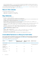
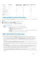
Feature iDRAC Basic iDRAC Express (Rack and Tower Servers) iDRAC Express (Blade Servers) iDRAC Enterprise Local updates Yes Yes Yes Yes Driver packs Yes Yes Yes Yes Hardware inventory Yes Yes Yes Yes Remote services (through WS-MAN) — Yes Yes Yes SupportAssist Collection Yes Yes Yes Yes Repurpose or retire system Yes Yes Yes Yes Viewing iDRAC license information After you open the Lifecycle Controller GUI page, you can view details about the iDRAC installed on a server.
• • The Glossary provides information about the terms used in this document. The OpenManage Server Update Utility User's Guide provides information about using the DVD-based application for identifying and applying updates to the system. The following system documents are available to provide more information: • • • • • The safety instructions that came with your system provide important safety and regulatory information.
Contacting Dell NOTE: If you do not have an active Internet connection, you can find contact information on your purchase invoice, packing slip, bill, or Dell product catalog. Dell provides several online and telephone-based support and service options. Availability varies by country and product, and some services may not be available in your area. To contact Dell for sales, technical support, or customer service issues: 1. Go to www.dell.com/support. 2. Select your support category. 3.
2 Using Lifecycle Controller This section provides information about starting, enabling, and disabling Lifecycle Controller. Before using Lifecycle Controller, make sure that the network and iDRAC are configured. For more information, see the Integrated Dell Remote Access Controller User’s Guide at www.dell.com/esmmanuals.
Message Cause Resolution retry. You can use the iDRAC GUI to check the job queue and the status. Enabling Lifecycle Controller To enable access to Lifecycle Controller during system startup: 1. Press during POST. The System Setup Main Menu page is displayed. 2. Select iDRAC Settings. The iDRAC Settings page is displayed. 3. Select Lifecycle Controller. 4. Under Lifecycle Controller, select Enabled. 5. On the System Setup Main Menu page, select Finish to save the settings. 6.
Setting up Lifecycle Controller using Initial Setup Wizard Use the Initial Setup Wizard to select the language and default keyboard settings, configure network settings, iDRAC network and credential configuration, and view the summary of the settings. Specifying language and keyboard type 1. Start Lifecycle Controller. For more information, see Starting Lifecycle Controller. 2. On the left pane, click Settings. 3. On the Settings pane, click Language and Keyboard.
• Static — indicates that the network must be configured by using a static IP. Type the IP Address Properties such as IP Address, Subnet Mask, Default Gateway, DNS Address Source, and DNS Address. If you do not have this information, contact your network administrator. • DHCP — indicates that the NIC must be configured using an IP address from a DHCP server. DHCP is the default option and the DHCP IP address is displayed on the Network Settings page. 2.
Accessing help Each Lifecycle Controller page has a help associated with it. Press or click Help (in the upper-right corner) to view the help information about the features available on a page. Viewing release notes 1. To view the release notes, click About on any page of Lifecycle Controller. NOTE: The About option is not available from the help pages. 2. Click View Release Notes.
Lifecycle Controller features This section provides a brief description about the Lifecycle Controller features and helps you understand how to use the Lifecycle Controller wizards most effectively. Each feature is a wizard in Lifecycle Controller, which supports the following tasks: • • • • • • • • Home — Navigate back to the Home page. Lifecycle Log — View and export the Lifecycle Controller log, and add a work note to the log.
3 Operating system deployment The OS Deployment feature allows you to deploy standard and custom operating systems on the managed system. You can also configure RAID before installing the operating system if it is not already configured. Lifecycle Controller allows deploying the operating system using the following options: • • • Manual installation Unattended installation. For more information on unattended installation, see Unattended installation UEFI Secure Boot.
• • • Boot Mode — Choose either UEFI or BIOS boot mode depending on the boot configuration of the system for OS installation. Secure Boot — Allows you to enable or disable the Secure Boot option. Click Enabled to secure the boot process by checking if the drivers are signed with an acceptable digital signature. This option is available only for the UEFI boot mode.
Configuring RAID using the operating system deployment wizard To configure RAID using the OS Deployment page: NOTE: If the system has a RAID controller, you can configure a virtual disk as the boot device. Create boot virtual disk only from disk drives populated across 0–3 of the system. For slot information, see the system Owner’s Manual at www.dell.com/support. 1. Start Lifecycle Controller. For more information, see Starting Lifecycle Controller. 2. In the left pane, click OS Deployment. 3.
Driver access Lifecycle Controller provides a local repository for drivers that are required for installing the operating system. Based on the operating system you want to install, the OS Deployment wizard extracts these drivers and copies them to a temporary directory (OEMDRV) on the managed system. These files are deleted after 18 hours or when you: • • Refresh the AC power cycle, which resets the iDRAC. Press select iDRAC Settings or Lifecycle Controller to cancel the Lifecycle Controller actions.
4 Monitor Using Lifecycle Controller, you can monitor the hardware inventory and events of a server throughout its life cycle.
Viewing hardware inventory — current or factory shipped NOTE: For factory-shipped inventory, the status of few parameters for the installed components is displayed as Unknown. To view the currently installed or factory-installed hardware components and their configuration details: 1. Start Lifecycle Controller. For more information, see Starting Lifecycle Controller. 2. In the left pane, click Hardware Configuration. 3. In the right pane, click Hardware Inventory. 4.
2. In the File Path box, type a valid directory or subdirectory path on the device. For example, 2015\Nov. If the path is not provided, the file is stored in the root location of the device. NOTE: Lifecycle Controller allows 256 characters in a path that includes the file name and file extension. For example, if 56 characters are used for file name and extension, only 200 characters can be used for the path. Lifecycle Controller does not support these characters -:, *,?,”,<,>,|,#,%,^, and SPACE.
1. Start Lifecycle Controller. For more information, see Starting Lifecycle Controller 2. In the left pane, click Hardware Configuration. 3. In the right pane, click Hardware Inventory. 4. Click View Current Inventory. Lifecycle Controller displays the old hardware inventory. 5. Restart the server and relaunch Lifecycle Controller. 6.
The following details are displayed: • • No. — The serial number of the event. Category — The category to which the events belong. The available categories are: • All — Events related to all categories are listed. • • • • • • System Health — Events related to the installed hardware such as fan, PSUs, NIC/LOM/CNA link, BIOS errors, and so on. Storage — Events related to the external or internal storage components such as storage controller, enclosure, HDDs, and software RAID.
Exporting Lifecycle Log to a USB drive To export the Lifecycle Log to a USB drive: 1. From the Select Device drop-down menu, select a USB drive. 2. In the File path box, type a valid directory or subdirectory path on the device. If the path is not provided, the file is stored in the root location of the device. For example, Logs\LCLogs. NOTE: Lifecycle Controller allows 256 characters in a path that includes the file name and file extension.
Adding a work note to the Lifecycle Log You can add a work note to the Lifecycle Log to record comments for your reference. You can enter comments such as scheduled downtime or changes made by administrators who work in different shifts for later reference. NOTE: You can type a maximum of 50 characters in the Lifecycle Log field. The special characters such as <, >, &, and % are not supported. To add a work note: 1. Start Lifecycle Controller. For more information, see Starting Lifecycle Controller. 2.
5 Firmware update With Lifecycle Controller, the system can be updated using the repositories accessible through FTP, a network share or on a locally attached USB drive or a DVD. Use the Firmware Update page to: • • • View the current version of the installed applications and firmware. View a list of available updates.
* Indicates that though a system restart is not required, iDRAC must be restarted to apply the updates. iDRAC communication and monitoring will temporarily be interrupted. ** The backplanes that cannot be updated are not listed. ***Applicable only for FX2 modular systems.
.D9 Image In-band OS DUP No iDRAC DUP N/A Yes No Version compatibility The version compatibility feature enables you to update the component firmware versions that are compatible with system components. In case of compatibility issues, Lifecycle Controller displays upgrade or downgrade error messages during the update. Updating firmware You can update to the latest version of Lifecycle Controller using the Firmware Update wizard.
NOTE: The system does not restart if operating system driver packs, OS collector tool, or hardware diagnostics are updated. NOTE: When applying more than one update, the system may restart between updates. In this case, Lifecycle Controller restarts the server and automatically continues the update process. NOTE: iDRAC resets while updating iDRAC. If the iDRAC firmware update is interrupted for any reason, wait for up to 30 minutes before you attempt another firmware update.
NOTE: Lifecycle Controller allows 256 characters in a path that includes the file name and file extension. For example, if 56 characters are used for file name and extension, only 200 characters can be used for the path. Lifecycle Controller does not support these characters -:, *,?,”,<,>,|,#,%,^, and SPACE. Using a USB drive You can download the repository from the SUU DVD or from an FTP location to a USB drive, and then access the updates from this drive.
Using proxy FTP server Using Lifecycle Controller, you can update the firmware by using downloads.dell.com , or by using an internal FTP server, when you are connected to the Internet through a proxy server. Before performing an update using a proxy FTP server, make sure that the following prerequisites are met: • • • • The network settings are configured—Settings > Network Settings. The updates are downloaded using the Dell Repository Manager, and the repository is created on an internal FTP server.
NOTE: If the catalog file and DUP are downloaded from downloads.dell.com, do not copy them to a subdirectory. NOTE: Lifecycle Controller allows 256 characters in a path that includes the file name and file extension. For example, if 56 characters are used for file name and extension, only 200 characters can be used for the path. Lifecycle Controller does not support these characters -:, *,?,”,<,>,|,#,%,^, and SPACE.
NOTE: While using Lifecycle Controller to update the Power Supply Unit (PSU) firmware, the system turns off after the first task. It takes a couple of minutes to update the PSU firmware, and then automatically turns on the server. Firmware rollback Lifecycle Controller allows you to roll back to a previously installed version of component firmware such as BIOS, iDRAC with Lifecycle Controller, RAID Controller, NIC, Enclosure, Backplane, Fibre Channel cards, BOSS-S1, NVDIMM, and Power Supply Unit (PSU).
Updating or rolling back devices that affect Trusted Platform Module settings Enabling Trusted Platform Module (TPM) with pre-boot measurement enables the BitLocker protection on the system. When BitLocker protection is enabled, updating or rolling back the components such as RAID controller, NIC, and BIOS require that a recovery password is entered or a USB drive that contains a recovery key is inserted during the next system restart.
6 Configure Lifecycle Controller provides various system configuration wizards. Use the configuration wizards to configure system devices. The Configuration Wizards has: • • System Configuration Wizards — This wizard includes LCD Panel Security, iDRAC Settings, and System Date and Time Configuration. Storage Configuration Wizards — This wizard includes RAID Configuration, Key Encryption, and Break Mirror.
Configuring iDRAC To configure iDRAC parameters applicable to the system, such as LAN, common IP settings, IPv4, IPv6, Virtual Media, and LAN user configuration use the iDRAC Settings wizard. NOTE: You can also use the System Setup utility during startup for configuring iDRAC. For more information about the System Setup utility, see Using the System Setup Program and Boot Manager. To configure and manage the iDRAC parameters: 1. Start Lifecycle Controller.
2. In the left pane, click Hardware Configuration. 3. In the right pane, click Configuration Wizards. 4. Under Storage Configuration Wizards, click RAID Configuration to launch the wizard. The View Current RAID Configuration and Select Controller page is displayed. NOTE: BOSS-S1 controller is supported at RAID 1 level only. 5. Select the controller and click Next. The Select RAID Level page is displayed. 6. Select the RAID level and click Next. The Select Physical Disks page is displayed. 7.
• • • • • • • RAID 0 — Stripes data across the physical disks. RAID 0 does not maintain redundant data. When a physical disk fails in a RAID 0 virtual disk, there is no method for rebuilding the data. RAID 0 offers good read and write performance with zero data redundancy. RAID 1 — Mirrors or duplicates data from one physical disk to another. If a physical disk fails, data can be rebuilt using the data from the other side of the mirror.
• T10 Protection Information (T10 PI) Capability— It is known as DIF (Data Integrity Fields) and the supporting HDDs are referred to DIF drives. The T10 enabled HDDs validates and stores the data integrity fields for each block. It performs this action when you write the data on the disk and return these values on a read request. When you read or write the data from the HDD, the data is checked for the errors.
Viewing summary The Summary page displays the virtual disk attributes based on selections. CAUTION: Clicking Finish deletes all existing virtual drives except any foreign configurations that you specified. All data residing on the virtual drives is lost. To return to a previous page to review or change selections, click Back. To close the wizard without making changes, click Cancel. Click Finish to create a virtual drive with the displayed attributes.
Creating a secure virtual disk on a RAID controller Make sure that the controller is set to use either Local Key Management (LKM) or Secure Enterprise Key Manager (SEKM). To create a secure virtual disk on a RAID controller: 1. Start Lifecycle Controller. For more information, see Starting Lifecycle Controller. 2. In the left pane, click Hardware Configuration. 3. In the right pane, click Configuration Wizards. 4. Under Storage Configuration Wizards, click RAID Configuration to launch the wizard.
8. In the New Passphrase field, enter a passphrase. NOTE: The controller uses the passphrase to encrypt the disk drive data. A valid passphrase contains 8–32 characters. It must include a combination of uppercase and lowercase letters, numbers, and symbols without spaces. 9. In the Confirm Passphrase field, re-enter the passphrase, and then click Finish.
Removing encryption and deleting data To remove the encryption and delete the data on the virtual disks: CAUTION: The existing encryption, virtual drives, and all the data are permanently deleted. 1. Start Lifecycle Controller. For more information, see Starting Lifecycle Controller. 2. In the left pane, click Hardware Configuration. 3. In the right pane, click Configuration Wizards and click Key Encryption. 4. Select the controller on which you must remove the key that was applied and click Next. 5.
• • Enabled with PXE to use the NIC for PXE boot. Enabled with iSCSI to use the NIC to boot from an iSCSI target. Modifying device settings To modify device settings using the Advanced Hardware Configuration: NOTE: You can also modify the device settings by using the System Setup utility during startup. For more information about the System Setup utility, see Using the system setup program and boot manager. 1. Start Lifecycle Controller. For more information, see Starting Lifecycle Controller. 2.
• • The local FTP server must use the default port (21). You must use the Settings wizard to configure the network card on your system before accessing updates from the local FTP server. Copying repository to a local FTP server from the Dell EMC server Updates DVD To copy the repository: 1. Download the Dell EMC server Updates ISO image to your system from www.dell.com/support. 2. Copy the repository folder of the DVD to the root directory of the local FTP server. 3.
NOTE: A USB drive is not required for users, who have access to downloads.dell.com through a proxy server. For the latest updates, download the most recent Dell EMC server Updates ISO images for your system from www.dell.com/support. NOTE: Lifecycle Controller supports internal SATA optical drives, USB drives, and Virtual Media devices. If the installation media is corrupt or not readable, then Lifecycle Controller may be unable to detect the presence of a media.
NOTE: The SMB2 option-RequireSecuritySignature must be set to False. The command to set the value from PowerShell is Set-SmbServerConfiguration -RequireSecuritySignature $false. For more information on SMB2 support in iDRAC and LC, see the white paper available here. Now the selected folder is shared over network and it can be accessed over CIFS protocol by using the \\ \share_name folder path. NOTE: Ensure that the folder is accessible and folder names doesn't have any space.
7 Maintain Using Lifecycle Controller, you can maintain the health of a system throughout its life cycle using the features such as Part Replacement Configuration and Platform Restore.
• • • Dell diagnostics. Dell OS Driver Pack. A Local Key Management (LKM) passphrase, if the LKM–based storage encryption is enabled. However, you must provide the LKM passphrase after performing the restore operation. Security The contents of the backup image file cannot be accessed with any application, even if it is generated without a passphrase.
* The security information refers to the user credentials that are used to access the components. ** PSU firmware will be extracted from the backup file, but will not be applied as it can interrupt the restore process.
Exporting server profile to USB drive or network share Before exporting the server profile, make sure that the following pre-requisites are met: • • • • • A software license for the PowerEdge servers is installed on the server. For more information about managing licenses using the iDRAC web interface, go to Overview > Server > Licenses, and see iDRAC Online Help. vFlash SD card is installed in the system and must contain the backup image file. USB drive has a minimum free space of 384 MB.
2. In the left pane, select Platform Restore. 3. In the right pane, select Import Server Profile. 4. Select vFlash Secure Digital (SD) Card and click Next. 5. Select either Preserve or Delete. • • Preserve — Preserves the RAID level, virtual drive, and controller attributes. Delete — Deletes the RAID level, virtual drive, and controller attributes. 6.
1. The system if turned on, automatically turns off. If the system boots to an operating system, it attempts to perform a graceful shutdown. If it is not able to perform a graceful shutdown, it performs a forced shutdown after 15 minutes. 2. The system turns on and boots to System Services to perform firmware restore for supported devices (BIOS, storage controllers, and Add-in NIC cards). 3.
• System Erase does not clear the data from the Easy Restore flash memory. • Easy Restore does not back up other data such as firmware images, vFlash data, or add-in cards data. NOTE: For more information about Backup and Restore features, see the Methods to Save and Restore PowerEdge Server Configuration Settings and Firmware Images white paper at www.dell.
6. In the File Path field, enter the directory or subdirectory path, where the backup image file is stored on the selected device and click Finish. The license is imported, installed, and the following message is displayed: License successfully Imported. Part replacement configuration Use the Part Replacement feature to automatically update a new part to the firmware version or the configuration of the replaced part, or both.
• • • • PERC series 9 and 10 SAS series 7 and 8 System board Power Supply Unit (PSU) NOTE: PSUs support only firmware update and not part replacement. Repurpose or retire system You can erase selective system information by using the Lifecycle Controller Repurpose or Retire System option. This feature permanently deletes server and storage-related data on selected components of a server before you repurpose or retire a server. The selected components are then returned to their default state.
Performing hardware diagnostics To perform hardware diagnostics: 1. Start Lifecycle Controller. For more information, see www.dell.com/support 2. In the left pane of Lifecycle Controller, click Hardware Diagnostics. 3. In the right pane, click Run Hardware Diagnostics. The diagnostics utility is launched. 4. Follow the instructions on the screen. When the tests are complete, results of the diagnostics tests are displayed on the screen. To resolve the problems reported in the test results, search dell.
• Storage controller logs After Lifecycle Controller exports the SupportAssist Collection file, you can delete information that you do not want to share with technical support. Each time the data is collected, an event is recorded in the Lifecycle Controller Log. The event includes information such as the interface used, the date and time of export, and iDRAC user name.
8 Easy-to-use system component names The following is the list of most commonly used Fully Qualified Device Descriptors (FQDD) used in all the interfaces including GUI, iDRAC RESTful API with Redfish, WSMAN, and RACADM. • • • • • • • • • • • • ALL iDRAC System LifecycleController EventFilters BIOS NIC FC RAID NVDIMM BOSS-S1 BOSS DISK The following table lists the FQDD of the system components and the equivalent easy-to-use names. Table 13.
FQDD of System Component Name Easy-to-use Name ISABridge.Embedded.1-1 Embedded ISA Bridge 2 P2PBridge.Embedded.1-1 Embedded P2P Bridge 3 P2PBridge.Mezzanine.2B-1 Embedded Host Bridge in Mezzanine 1 (Fabric B) USBUHCI.Embedded.1-1 Embedded USB UHCI 1 USBOHCI.Embedded.1-1 Embedded USB OHCI 1 USBEHCI.Embedded.1-1 Embedded USB EHCI 1 Disk.SATAEmbedded.A-1 Disk on Embedded SATA Port A Optical.SATAEmbedded.B-1 Optical Drive on Embedded SATA Port B TBU.SATAExternal.
FQDD of System Component Name Easy-to-use Name Fan.Slot. 9 Fan 9 MC.Chassis.1 Chassis Management Controller 1 MC.Chassis.2 Chassis Management Controller 2 KVM.Chassis.1 KVM IOM.Slot.1 IO Module 1 IOM.Slot.2 IO Module 2 IOM.Slot.3 IO Module 3 IOM.Slot.4 IO Module 4 IOM.Slot.5 IO Module 5 IOM.Slot.6 IO Module 6 PSU.Slot.1 Power Supply 1 PSU.Slot.2 Power Supply 2 PSU.Slot.3 Power Supply 3 PSU.Slot.4 Power Supply 4 PSU.Slot.5 Power Supply 5 PSU.Slot.6 Power Supply 6 CPU.Socket.
9 Using the system setup and boot manager System Setup enables you to manage your system hardware and specify BIOS-level options. The following keystrokes provide access to system features during startup: Table 14. System setup keystrokes Keystroke Description Opens the System Setup page. Opens and starts Lifecycle Controller, which supports systems management features such as operating system deployment, hardware diagnostics, firmware updates, and platform configuration, using a GUI.
NOTE: The system supports only BIOS boot mode. 1. From the System Setup Main Menu, click Boot Settings, and select Boot Mode. 2. Select the UEFI boot mode you want the system to boot into. CAUTION: Switching the boot mode may prevent the system from booting if the operating system is not installed in the same boot mode. 3. After the system boots in the specified boot mode, proceed to install your operating system from that mode.
System Setup options System Setup Main screen NOTE: Press to reset the BIOS or UEFI settings to their default settings. Menu item Description System BIOS This option is used to view and configure BIOS settings. iDRAC Settings This option is used to view and configure iDRAC settings. Device Settings This option is used to view and configure device settings. System BIOS screen NOTE: The options for System Setup change based on the system configuration.
Menu Item Description System Manufacturer Displays the name of the system manufacturer. System Manufacturer Contact Information Displays the contact information of the system manufacturer. Memory Settings screen Menu Item Description System Memory Size Displays the amount of memory installed in the system. System Memory Type Displays the type of memory installed in the system. System Memory Speed Displays the system memory speed. System Memory Voltage Displays the system memory voltage.
Menu Item Description Transaction ID) Setting Virtualization Technology Allows you to enable or disable the additional hardware capabilities provided for virtualization. By default, the Virtualization Technology option is set to Enabled. Adjacent Cache Line Prefetch Allows you to optimize the system for applications that require high utilization of sequential memory access. By default, the Adjacent Cache Line Prefetch option is set to Enabled.
Menu Item Description Port E Auto enables BIOS support for the device attached to SATA port E. By default, Port E is set to Auto. Port F Auto enables BIOS support for the device attached to SATA port F. By default, Port F is set to Auto. NOTE: Ports A, B, C, and D are used for the backplane drives, port E for the optical drive (CD/DVD), and port F for the tape drive. Boot Settings screen Menu item Description Boot Mode Allows you to set the boot mode of the system.
Menu Item Description Embedded Video Controller Allows you to enable or disable the Embedded Video Controller. By default, the embedded video controller is set to Enabled. SR-IOV Global Enable Allows you to enable or disable the BIOS configuration of Single Root I/O Virtualization (SR-IOV) devices. By default, the SR-IOV Global Enable option is set to Disabled. Memory Mapped I/O above 4GB Allows you to enable support for PCIe devices that require large amounts of memory.
Option Description Memory Frequency Sets the speed of the system memory. You can select Maximum Performance, Maximum Reliability, or a specific speed. Turbo Boost Enables or disables the processor to operate in turbo boost mode. This option is set to Enabled by default. C States Enables or disables the processor to operate in all available power states. This option is set to Enabled by default. Monitor/Mwait Enables the Monitor/Mwait instructions in the processor.
Menu Item Description Power Button Allows you to enable or disable the power button on the front of the system. By default, the Power Button option is set to Enabled. NMI Button Allows you to enable or disable the NMI button on the front of the system. By default, the NMI Button option is set to Disabled. AC Power Recovery Allows you to set how the system reacts after AC power is restored to the system. By default, the AC Power Recovery option is set to Last.
NOTE: You can assign a new system password or setup password or change an existing system password or setup password only when the password jumper setting is enabled and Password Status is set to Unlocked. If the Password Status is set to Locked, you cannot change the system password or setup password. If the password jumper setting is disabled, the existing system password and setup password is deleted and you need not provide the system password to boot the system. 1.
2. Type the system password and press Enter. When Password Status is set to Locked, type the system password and press Enter when prompted at reboot. NOTE: If an incorrect system password is typed, the system displays a message and prompts you to reenter your password. You have three attempts to type the correct password. After the third unsuccessful attempt, the system displays an error message that the system has stopped functioning and must be turned off.
Key Description NOTE: For the standard graphics browser only. Moves to the previous page till you view the main screen. Pressing in the main screen exits the Boot Manager and proceeds with system boot. Displays the System Setup help file. NOTE: For most of the options, any changes that you make are recorded but do not take effect until you restart the system.
For more information on using iDRAC, see iDRAC User's Guide available at www.dell.com/idracmanuals . Entering the iDRAC settings utility 1. Turn on or restart the managed system. 2. Press during POST. 3. In the System Setup Main Menu page, click iDRAC Settings. The iDRAC Settings screen is displayed.
10 Troubleshooting and frequently asked questions This section describes the error messages commonly generated by Lifecycle Controller and provides suggestions for resolving the issues. This section also lists the questions that are frequently asked by Lifecycle Controller users. Topics: • • Error messages Frequently asked questions Error messages Each error message that is generated from Lifecycle Controller has a Message ID, Message Description, and Recommended Response Action in a single dialog box.
11. What is UEFI? With which version of UEFI does Lifecycle Controller comply? Unified Extensible Firmware Interface (UEFI) is a specification that defines a model for the interface between the operating systems and firmware on a server. The interface consists of data tables that contain platform-related information, along with boot and runtime calls available to the operating system and operating system loaders.