Inspiron 14 Owner's Manual Regulatory Model: P41G Regulatory Type: P41G002
Notes, Cautions, and Warnings NOTE: A NOTE indicates important information that helps you make better use of your computer. CAUTION: A CAUTION indicates either potential damage to hardware or loss of data and tells you how to avoid the problem. WARNING: A WARNING indicates a potential for property damage, personal injury, or death. © 2013 Dell Inc.
Contents 1 Working on Your Computer.................................................................................5 Before Working Inside Your Computer.............................................................................................5 Turning Off Your Computer..............................................................................................................6 After Working Inside Your Computer.............................................................................................
3 System Setup........................................................................................................ 35 System Setup Overview...................................................................................................................35 Boot Sequence................................................................................................................................ 35 Navigation Keys...........................................................................................
Working on Your Computer 1 Before Working Inside Your Computer Use the following safety guidelines to help protect your computer from potential damage and to help to ensure your personal safety. Unless otherwise noted, each procedure included in this document assumes that the following conditions exist: • You have read the safety information that shipped with your computer. • A component can be replaced or--if purchased separately--installed by performing the removal procedure in reverse order.
3. Disconnect all network cables from the computer. 4. Disconnect your computer and all attached devices from their electrical outlets. 5. Press and hold the power button while the computer is unplugged to ground the system board. 6. Remove the cover. CAUTION: Before touching anything inside your computer, ground yourself by touching an unpainted metal surface, such as the metal at the back of the computer.
5. If required, verify that the computer works correctly by running the Dell Diagnostics.
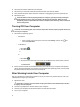
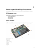
Removing and Installing Components 2 This section provides detailed information on how to remove or install the components from your computer. Recommended Tools The procedures in this document may require the following tools: • Small flat-blade screwdriver • Phillips screwdriver • Small plastic scribe System Overview The figure below displays the inside view of the back of the computer after the base cover has been removed.
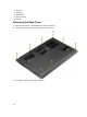
7. hard drive 8. system fan 9. system board 10. memory module 11. heatsink Removing the Base Cover 1. Follow the procedures in Before Working Inside Your Computer. 2. Remove the screws that secure the base cover to the computer. 3. Pry the base cover along the edges to loosen it.
4. Lift and remove the base cover from the computer.
Installing the Base Cover 1. Place the base cover to align with the screw holes on the computer. 2. Tighten the screws to secure the base cover to the computer. 3. Follow the procedures in After Working Inside Your Computer. Removing the Battery 1. Follow the procedures in Before Working Inside Your Computer. 2. Remove the base cover. 3. Disconnect the battery cable from its connector on the system board.
4. Release the tabs that secure the battery in the battery bay. 5. Lift and remove the battery from the computer.
Installing the Battery 1. Place the battery into its slot until it clicks into place. 2. Connect the battery cable to its connector on the system board. 3. Install the base cover. 4. Follow the procedures in After Working Inside Your Computer. Removing the Hard Drive 1. Follow the procedures in Before Working Inside Your Computer. 2. Remove: a) base cover b) battery 3. 14 Lift the hard drive assembly in an upward direction to release it from its compartment on the computer.
4. Lift and remove the hard drive from the computer..
Installing the Hard Drive 1. Place the hard drive assembly into its slot on the computer. 2. Install: a) battery b) base cover 3. Follow the procedures in After Working Inside Your Computer. Removing the Coin-Cell Battery 1. Follow the procedures in Before Working Inside Your Computer. 2. Remove : a) base cover b) battery 3. Perform the steps as shown in the illustration: a) Disconnect the coin-cell battery cable from its connector on the system board.
a) Disconnect the antenna cable from the WLAN card. b) Remove the screw that secures the WLAN card to the computer. c) Remove the WLAN card from its slot on the system board. Installing the WLAN Card 1. Insert the WLAN card into its connector at a 45–degree angle. 2. Tighten the screw to secure the WLAN card to the computer. 3. Connect the antenna cables to their respective connectors marked on the WLAN card. 4. Install: a) battery b) base cover 5.
Removing the System Fan 1. Follow the procedures in Before Working Inside Your Computer. 2. Remove: a) base cover b) battery 3. Perform the steps as shown in the illustration: a) Disconnect the left system fan cable from its connector on the system board. b) Remove the screws that secure the left system fan to the system board. 4. 18 Lift and remove the left system fan from the computer.
5. Disconnect the right system fan cable from its connector on the system board. Peel away the system board flex cable from the right system fan. 6. Remove the screws that secure the right system fan to the system board.
7. 20 Lift and remove the right system fan from the computer.
Installing the System Fan 1. Place the right system fan into its original position in the system board and affix the system board flex cable. 2. Tighten the screws that secure the right system fan to the system board. 3. Connect the right system fan cable to its connector on the system board. 4. Place the left system fan into its original position in the system board. 5. Tighten the screws that secure the left system fan to the system board. 6.
Installing the Heatsink 1. Place the heatsink into its original position on the system board. 2. Tighten the screws to secure the heatsink to the system board. 3. Install: a) system fan b) battery c) base cover 4. Follow the procedures in After Working Inside Your Computer. Removing the Memory 1. Follow the procedures in Before Working Inside Your Computer. 2. Remove: a) base cover b) battery 3. 22 Pry the securing clips away from the memory module until it pops up.
Installing the Memory 1. Insert the memory module into the memory socket. 2. Press the memory module down until it clicks into place. 3. Install: a) battery b) base cover 4. Follow the procedures in After Working Inside Your Computer. Removing the System Board 1. Follow the procedures in Before Working Inside Your Computer. 2. Remove: a) base cover b) battery c) system fan d) heatsink e) hard drive 3.
4. Remove the screws that secure the system board to the chassis. 5. Remove the system board from the computer.
Installing the System Board 1. Place the system board into its original position on the chassis. 2. Tighten the screws to secure the system board to the chassis. 3. Connect the following cable: a) b) c) d) e) f) g) h) 4. Install: a) b) c) d) e) 5. finger printer WLAN coin-cell battery camera touchpad keyboard display speaker hard drive heatsink system fan battery base cover Follow the procedures in After Working Inside Your Computer. Removing the Speakers 1.
4. 26 Lift the speaker assembly along with the routing cable and remove the speakers from the computer.
Installing the Speakers 1. Place the speakers into its original position on the computer. 2. Route the speaker cable along the routing channel. 3. Connect the speaker connector to its slot on the system board. 4. Install: a) b) c) d) e) f) g) h) i) 5. system board heatsink system fan coin-cell battery mSATA SSD card WLAN card hard drive battery base cover Follow the procedures in After Working Inside Your Computer. Removing the Display Assembly 1.
4. Remove the screws that secure the display hinges to the system board. Lift and move the system base panel away from the display hinges to facilitate easy removal of the display assembly. 5. Remove the system base panel.
Installing the Display Assembly 1. Align the base panel of the computer to the display hinges. 2. Install the screws that secure the display hinges to the system board. 3. Connect the LVDS cable and the camera cable to the connectors on the system board. 4. Install : a) battery b) base cover 5. Follow the procedures in After Working Inside Your Computer. Removing the Display Bezel 1. Follow the procedures in Before Working Inside Your Computer. 2.
4. Pry on the plastic caps that cover the display bezel screws and remove them. 5. Remove the screws that secure the screws to the display bezel.
6. Pry along the inner edges of the display bezel and remove the display bezel.
Installing the Display Bezel 1. Align the display bezel by pressing along the edges. 2. Install the screws that secure the display bezel. 3. Install the plastic caps that secure the display bezel screws on both sides of the display. 4. Install : a) battery b) base cover c) display assembly 5. Follow the procedures in After Working Inside Your Computer. Removing the Display Panel 1. Follow the procedures in Before Working Inside Your Computer. 2.
Installing the Display Panel 1. Align the display panel to the display assembly by pressing along the edges. 2. Install the screws that secure the display. 3. Install: a) b) c) d) 4. battery base cover display assembly display bezel Follow the procedures in After Working Inside Your Computer. Removing the Camera 1. Follow the procedures in Before Working Inside Your Computer. 2. Remove : a) b) c) d) e) 3.
Installing the Camera 1. Align the camera to the base panel . 2. Connect the camera cable to the camera. 3. Install : a) b) c) d) e) 4. 34 battery base cover display assembly display bezel display Follow the procedures in After Working Inside Your Computer.
System Setup 3 System Setup Overview System Setup allows you to: • change the system configuration information after you add, change, or remove any hardware in your computer. • set or change a user-selectable option such as the user password. • read the current amount of memory or set the type of hard drive installed. • check battery health. Before you use System Setup, it is recommended that you write down the System Setup screen information for future reference.
NOTE: For most of the system setup options, changes that you make are recorded but do not take effect until you restart the system. Table 1. Navigation Keys Keys Navigation Up arrow Moves to the previous field. Down arrow Moves to the next field. Allows you to select a value in the selected field (if applicable) or follow the link in the field. Spacebar Expands or collapses a drop‐down list, if applicable. Moves to the next focus area. NOTE: For the standard graphics browser only.
System Setup Options Main Table 2. Main System Time Re-sets the time on the computer's internal clock. System Date Re-sets the date on the computer's internal calendar. BIOS Version Displays the BIOS revision. Product Name Displays the product name and the model number. Service Tag Displays the service tag of your computer. Asset Tag Displays the asset tag of your computer (if available). CPU Type Displays the type of processor. CPU Speed Displays the speed of the processor.
SATA Operation Change the SATA controller mode to either ATA or AHCI. Default: AHCI Adapter Warnings Enable or disable the Adapter Warnings. Default: Enable Function Key Behavior Specifies the behavior of the function key . Default: Function key Intel Smart Connect Technology Enable or disable Intel Smart Connect Technology. Default: Enable Intel Rapid Start Technology Enable or disable Inter Rapid Start Technology.
This section allows you to save, discard, and load default settings before exiting from System Setup.
4 Troubleshooting Enhanced Pre-Boot System Assessment (ePSA) Diagnostics The ePSA diagnostics (also known as system diagnostics) performs a complete check of your hardware. The ePSA is embedded with the BIOS and is launched by the BIOS internally.
Battery Charge LED Off/Hibernate Standby Battery mode Discharging when Battery charge is > 10% Off Off Discharging when Battery charge is <=10% Off Blinking White Device Status Lights Turns on when you turn on the computer and blinks when the computer is in a power management mode. Turns on when the computer reads or writes data. Turns on steadily or blinks to indicate battery charge status.
Code Cause and Troubleshooting Steps 8 Display Display failure 43
Contacting Dell 5 Contacting Dell NOTE: If you do not have an active Internet connection, you can find contact information on your purchase invoice, packing slip, bill, or Dell product catalog. Dell provides several online and telephone-based support and service options. Availability varies by country and product, and some services may not be available in your area. To contact Dell for sales, technical support, or customer service issues: 1. Visit dell.com/support 2. Select your support category. 3.