
Service Manual


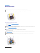


Screw Identification
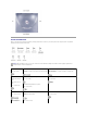
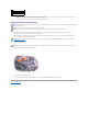
When you are removing and replacing components, photocopy the placemat as a tool to lay out and keep track of the component screws. The placemat
provides the number of screws and the sizes.
NOTICE: When reinstalling a screw, you must use a screw of the correct diameter and length. Ensure that the screw is properly aligned with its
corresponding hole, and avoid overtightening.
Hard-Drive Door Security:
M3 x 5 mm (1 each)
Keyboard to Bottom Case:
M2.5 x 20 mm (4 each; one in memory door and one in Mini
PCI door)
Display to Bottom Case:
M2.5 x 6 mm (3 each; 2 at back of computer; 1 at display flex-
cable strain relief)
Display Bezel:
Rubber screw covers (4
each)
Plastic screw covers (2
each)
M2.5 x 4 mm (6 each)
Display Panel to Display Mounting Bracket:
M2 x 3 mm (6 each)
Flex-Cable Mounting Bracket to Top Cover:
M2.5 x 4 mm (1 each)
Video Graphics Board:
M2.5 x 8 (3 each)
Palm Rest to
Bottom Case:
M2.5 x 20 mm (9 each)
Palm Rest Bracket:
M2.5 x 4 mm (4 each)
System Board:
M2.5 x 4 mm captive washer
(3 each)
M2.5 x 20 mm (1 each)
LED Board:
M2 x 4 mm (2 each)