Dell™ Inspiron™ XPS and Inspiron 9100 Service Manual Before You Begin Memory Module, Mini PCI Card, and Devices System Components Subwoofer Bluetooth™ Card Hard Drive Fans Hinge Covers Keyboard Modem Reserve Battery Display Assembly and Display Latch Keyboard Bracket Palm Rest Video Card Microprocessor Thermal-Cooling Assembly Microprocessor Module Speakers Display Release Latch System Board Flashing the BIOS Pin Assignments for I/O Connectors Notes, Notices, and Cautions NOTE: A NOTE indicates important
Back to Contents Page Before You Begin Dell™ Inspiron™ XPS and Inspiron 9100 Service Manual Preparing to Work Inside the Computer Recommended Tools Computer Orientation Screw Identification Preparing to Work Inside the Computer CAUTION: Only a certified service technician should perform repairs on your computer. Damage due to servicing that is not authorized by Dell is not covered by your warranty. Read and follow the safety instructions in the Owner's Manual that came with the computer.
11. Remove any installed memory modules, Mini PCI cards, and devices, including a second battery if one is installed. 12. Remove the hard drive.
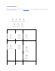
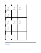
Screw Identification When you are removing and replacing components, photocopy "Screw Identification" as a tool to lay out and keep track of the screws. The placemat provides the number of screws and their sizes.
Display Ground Screw: Palm Rest: Video Card: Speakers: (3 each) (4 each) (3 each) (4 each) Display Release Latch: System Board: (2 each) (6 each) (1 each) Back to Contents Page
Back to Contents Page Flashing the BIOS Dell™ Inspiron™ XPS and Inspiron 9100 Service Manual 1. Ensure that the AC adapter is plugged in and that the main battery is installed properly. NOTE: If you use a BIOS update program CD to flash the BIOS, set up the computer to boot from a CD before inserting the CD. 2. Insert the BIOS update program floppy disk or CD, and turn on the computer. Follow the instructions that appear on the screen. The computer continues to boot and updates the new BIOS.
Back to Contents Page Bluetooth™ Card Dell™ Inspiron™ XPS and Inspiron 9100 Service Manual CAUTION: Before performing the following procedures, read the safety instructions in your Owner's Manual. NOTICE: To avoid electrostatic discharge, ground yourself by using a wrist grounding strap or by periodically touching an unpainted metal surface (such as the back panel) on the computer.
Back to Contents Page Microprocessor Module Dell™ Inspiron™ XPS and Inspiron 9100 Service Manual Removing the Microprocessor Module CAUTION: Before performing the following procedures, read the safety instructions in your Owner's Manual. NOTICE: To avoid electrostatic discharge, ground yourself by using a wrist grounding strap or by periodically touching an unpainted metal surface (such as the back panel) on the computer. NOTICE: Do not touch the processor die.
3 ZIF-socket cam screw 4 pin-1 corner NOTE: The ZIF-socket cam screw secures the microprocessor to the system board. Take note of the arrow on the ZIF-socket cam screw, which indicates the direction to turn the cam screw. 9. Lift out the microprocessor module. Installing the Microprocessor Module NOTICE: Ensure that the cam lock is in the fully open position before seating the microprocessor module. Seating the microprocessor module properly in the ZIF socket does not require force.
Back to Contents Page Display Assembly and Display Latch Dell™ Inspiron™ XPS and Inspiron 9100 Service Manual Display Bezel Display Panel Display Latch CAUTION: Before performing the following procedures, read the safety instructions in your Owner's Manual. NOTICE: To avoid electrostatic discharge, ground yourself by using a wrist grounding strap or by periodically touching an unpainted metal surface (such as the back panel) on the computer.
1 display cable 2 antenna cables (2) 3 system board connector 6. Use the pull-tab to disconnect the display cable. 7. Lift the display out of the computer at a 90-degree angle.
1 M2.5 x 6-mm screws (6) 5 display bezel 2 rubber display bumpers (6) 6 display panel 3 M2.5 x 6-mm shoulder screws (2) 7 display base 4 screw covers (2) 8 M2.5 x 3-mm screws (8) Display Bezel CAUTION: Before performing the following procedures, read the safety instructions in your Owner's Manual. NOTICE: To avoid electrostatic discharge, ground yourself by using a wrist grounding strap or by periodically touching an unpainted metal surface (such as the back panel) on the computer.
1 M2.5 x 6-mm screws (6) 2 rubber display bumpers (6) 3 display bezel 4 M2.5 x 6-mm shoulder screws (2) 5 screw covers (2) Display Panel CAUTION: Before performing the following procedures, read the safety instructions in your Owner's Manual. NOTICE: To avoid electrostatic discharge, ground yourself by using a wrist grounding strap or by touching an unpainted metal surface on the computer.
1 display-panel ground wire 2 M2 x 3-mm ground screw 3 M2 x 3-mm screws (8) 4 display panel 7. Press in both sides of the top flex-cable connector, and pull the top flex-cable connector away from the display connector. 8. Use the pull-tab to disconnect the bottom flex-cable connector from the inverter connector.
1. Follow the instructions in "Preparing to Work Inside the Computer." 2. Remove the display. 3. Remove the display bezel. 4. Remove the two M2.5 x 4-mm screws and remove the display latch. 1 M2.
Back to Contents Page Fans Dell™ Inspiron™ XPS and Inspiron 9100 Service Manual CAUTION: Before performing the following procedures, read the safety instructions in your Owner's Manual. NOTICE: To avoid electrostatic discharge, ground yourself by using a wrist grounding strap or by periodically touching an unpainted metal surface (such as the back panel) on the computer. NOTICE: To avoid damaging the system board, you must remove the main battery before you begin working inside the computer.
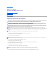
1 fan 2 fan release lever 3 M2.5 x 6-mm screw 5. Use the fan release lever to lift the fan out of the computer. When replacing fan 2, press down on the fan surface labeled "Press here" to securely seat the fan in place. To remove fan 3: 1. Unscrew the two captive screws labeled "F3." 2. Lift the fan out of the computer. NOTE: The cover on this fan is not removable. It remains attached to the fan.
Back to Contents Page Hard Drive Dell™ Inspiron™ XPS and Inspiron 9100 Service Manual CAUTION: If you remove the hard drive from the computer when the drive is hot, do not touch the metal housing of the hard drive. CAUTION: Before working inside your computer, read the safety instructions in your Owner's Manual. NOTICE: To avoid damaging the system board, you must remove the main battery before you begin working inside the computer.
6. Replace and tighten the screw. 7. Use the Operating System CD to install the operating system for your computer. For instructions, see "Reinstalling Microsoft Windows XP" in your Owner's Manual. 8. Use the Drivers and Utilities CD to install the drivers and utilities for your computer. For instructions, see "Reinstalling Drivers and Utilities" in your Owner's Manual. Returning a Hard Drive to Dell Return your old hard drive to Dell in its original or comparable foam packaging.
Back to Contents Page Hinge Covers Dell™ Inspiron™ XPS and Inspiron 9100 Service Manual CAUTION: Before working inside your computer, read the safety instructions in your Owner's Manual. NOTICE: To avoid electrostatic discharge, ground yourself by using a wrist grounding strap or by periodically touching an unpainted metal surface (such as the back panel) on the computer. NOTICE: To avoid damaging the system board, you must remove the main battery before you begin working inside the computer.
1 hinge cover snaps (2) c. Open the display all the way (180 degrees) so that it lies flat against your work surface. d. Lift the center hinge cover just enough to access the flex-cable connector. e. Using the pull-tab, disconnect the center–hinge-cover flex cable from the system board connector.
Back to Contents Page Keyboard Dell™ Inspiron™ XPS and Inspiron 9100 Service Manual CAUTION: Before performing the following procedures, read the safety instructions in your Owner's Manual. NOTICE: To avoid electrostatic discharge, ground yourself by using a wrist grounding strap or by periodically touching an unpainted metal surface (such as the back panel) on the computer. NOTICE: To avoid damaging the system board, you must remove the main battery before you begin working inside the computer.
Back to Contents Page
Back to Contents Page Keyboard Bracket Dell™ Inspiron™ XPS and Inspiron 9100 Service Manual CAUTION: Before performing the following procedures, read the safety instructions in your Owner's Manual. NOTICE: To avoid electrostatic discharge, ground yourself by using a wrist grounding strap or by periodically touching an unpainted metal surface (such as the back panel) on the computer.
Back to Contents Page Display Release Latch Dell™ Inspiron™ XPS and Inspiron 9100 Service Manual CAUTION: Before performing the following procedures, read the safety instructions in your Owner's Manual. NOTICE: To avoid electrostatic discharge, ground yourself by using a wrist grounding strap or by periodically touching an unpainted metal surface (such as the back panel) on the computer.
Back to Contents Page Modem Dell™ Inspiron™ XPS and Inspiron 9100 Service Manual CAUTION: Before performing the following procedures, read the safety instructions in your Owner's Manual. NOTICE: To avoid electrostatic discharge, ground yourself by using a wrist grounding strap or by periodically touching an unpainted metal surface (such as the back panel) on the computer. NOTICE: To avoid damaging the system board, you must remove the main battery before you begin working inside the computer.
NOTICE: Ensure that the modem cable is routed correctly when you replace the modem. NOTICE: Do not press down on the left side of the modem while installing it. 2. Align the connector on the bottom of the modem with the modem connector on the system board and then press down on the right side of the modem to seat both connectors. 3. Replace the M2.5 x 3-mm screw.
Back to Contents Page Palm Rest Dell™ Inspiron™ XPS and Inspiron 9100 Service Manual CAUTION: Before performing the following procedures, read the safety instructions in your Owner's Manual. NOTICE: To avoid electrostatic discharge, ground yourself by using a wrist grounding strap or by periodically touching an unpainted metal surface (such as the back panel) on the computer. NOTICE: To avoid damaging the system board, you must remove the main battery before you begin working inside the computer.
1 M2.
Back to Contents Page Pin Assignments for I/O Connectors Dell™ Inspiron™ XPS and Inspiron 9100 Service Manual USB Connector Video Connector S-Video TV-Out Connector IEEE 1394 Connector DVI-I Connector USB Connector Pin Signal 1 USB5V+ 2 USBP– 3 USBP+ 4 GND Video Connector Pin Signal Pin Signal 1 CRT_R 9 5V+ 2 CRT_G 10 GND 3 CRT_B 11 MONITOR_DETECT– 4 NC 12 DDC_DATA 5 GND 13 CRT_HS 6 GND 14 CRT_VS 7 GND 15 DDC_CLK 8 G
S-Video Pin Signal 1 GND 2 GND 3 DLUMA-L 4 DCRMA-L Composite Video Pin Signal 5 NC 6 DCMPS-L 7 GND IEEE 1394 Connector Pin Signal 1 TPB– 2 TPB+ 3 TPA– 4 TPA+ DVI-I Connector Pin Signal Pin Signal 1 TMDS DATA2– 13 TMDS DATA3+ 2 TMDS DATA2+ 14 +5V 3 TMDS DATA2/4 SHLD 15 GND (FOR +5V) 4 TMDS DATA4– 16 HOT PLUG DETECT 5 TMDS DATA4+ 17 TMDS DATA0– 6 DDC CLK 18 TMDS DATA0+
7 DDC DATA 19 TMDS DATA0/5 SHLD 8 ANALOG VERT SYNC 20 TMDS DATA5– 9 TMDS DATA1– 21 TMDS DATA5+ 10 TMDS DATA1+ 22 TMDS CLK SHLD 11 TMDS DATA1/3 SHLD 23 TMDS CLK+ 12 TMDS DATA3– 24 TMDS CLK– Pin Signal C1 ANALOG RED VID OUT C2 ANALOG GRN VID OUT C3 ANALOG BLU VID OUT C4 ANALOG HOR SYNC C5 ANALOG COM GND RET Back to Contents Page
Back to Contents Page Reserve Battery Dell™ Inspiron™ XPS and Inspiron 9100 Service Manual CAUTION: Before performing the following procedures, read the safety instructions in your Owner's Manual. NOTICE: To avoid electrostatic discharge, ground yourself by using a wrist grounding strap or by periodically touching an unpainted metal surface (such as the back panel) on the computer.
Back to Contents Page Speakers Dell™ Inspiron™ XPS and Inspiron 9100 Service Manual CAUTION: Before performing the following procedures, read the safety instructions in your Owner's Manual. NOTICE: To avoid electrostatic discharge, ground yourself by using a wrist grounding strap or by periodically touching an unpainted metal surface (such as the back panel) on the computer. NOTICE: To avoid damaging the system board, you must remove the main battery before you begin working inside the computer.
Back to Contents Page System Board Dell™ Inspiron™ XPS and Inspiron 9100 Service Manual Removing the System Board CAUTION: Before performing the following procedures, read the safety instructions in your Owner's Manual. NOTICE: To avoid electrostatic discharge, ground yourself by using a wrist grounding strap or by periodically touching an unpainted metal surface (such as the back panel) on the computer.
1 M2.5 x 6-mm screws (4) 2 system board top assembly 12. With the front of the computer facing you, lift the system board assembly from the right side, swinging it up, then lift the left side and draw the system board assembly out of the computer. 1 system board assembly Installing the System Board 1. Perform all of the steps in "Removing the System Board" in reverse order.
Back to Contents Page System Components Dell™ Inspiron™ XPS and Inspiron 9100 Service Manual NOTICE: Only a certified service technician should perform repairs on your computer. Damage due to servicing that is not authorized by Dell is not covered by your warranty. NOTICE: Unless otherwise noted, each procedure in this document assumes that a part can be replaced by performing the removal procedure in reverse order.
Back to Contents Page Microprocessor Thermal-Cooling Assembly Dell™ Inspiron™ XPS and Inspiron 9100 Service Manual Removing the Microprocessor Thermal-Cooling Assembly CAUTION: Before performing the following procedures, read the safety instructions in your Owner's Manual. NOTICE: To avoid electrostatic discharge, ground yourself by using a wrist grounding strap or by periodically touching an unpainted metal surface (such as the back panel) on the computer.
Back to Contents Page Memory Module, Mini PCI Card, and Devices Dell™ Inspiron™ XPS and Inspiron 9100 Service Manual Memory Module Mini PCI Card Devices Memory Module CAUTION: Before working inside your Dell™ computer, read the safety instructions in your Owner's Manual. CAUTION: To prevent static damage to components inside your computer, discharge static electricity from your body before you touch any of your computer's electronic components.
NOTICE: Ensure that memory modules are installed in both connectors and that they are of the same capacity. Install a memory module in the connector labeled "DIMM A" before you install a module in the connector labeled "DIMM B." Insert memory modules at a 45-degree angle to avoid damaging the connector. 4. Ground yourself and install the new memory module: a. Align the notch in the module edge connector with the tab in the connector slot. b.
CAUTION: Before working inside your computer, read the safety instructions in your Owner's Manual. NOTICE: To avoid damaging the system board, you must remove the main battery before you begin working inside the computer. NOTE: 2.4-GHz Wireless LAN PC Cards may be removed and installed by the user. If you ordered a Mini PCI card with your computer, the card is already installed. 1. Follow the instructions in "Preparing to Work Inside the Computer." 2. Turn over the computer. 3.
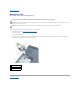
1 securing tabs NOTICE: To avoid damaging the antenna cables or the Mini PCI card, never place the cables under the card. NOTICE: The connectors are keyed to ensure correct insertion. If you feel resistance, check the connectors and realign the card. 5. Align the Mini PCI card with the connector at a 45-degree angle, and press the Mini PCI card into the connector until it clicks. 6. Connect the antenna cables to the Mini PCI card.
1 antenna cables 7. Replace the cover and tighten the captive screw. Devices Your computer ships with an optical drive installed in the module bay. NOTICE: Insert devices into the module bay before you dock and turn on the computer. Removing and Installing Devices While the Computer Is Turned Off NOTICE: To prevent damage to devices, store them in a safe, dry place when they are not installed in the computer. Avoid pressing down on them or placing heavy objects on top of them. 1.
1 module bay device 2 device latch release 3. Push the new device into the bay until it clicks. Removing and Installing Devices While the Computer Is Running 1. Before ejecting the device, double-click the Safely Remove Hardware icon on the taskbar, click the device you want to eject, and click Stop. NOTICE: To prevent damage to devices, store them in a safe, dry place when they are not installed in the computer. Avoid pressing down on them or placing heavy objects on top of them. 2.
Back to Contents Page
Back to Contents Page Video Card Dell™ Inspiron™ XPS and Inspiron 9100 Service Manual CAUTION: Before performing the following procedures, read the safety instructions in your Owner's Manual. NOTICE: To avoid electrostatic discharge, ground yourself by using a wrist grounding strap or by periodically touching an unpainted metal surface (such as the back panel) on the computer. NOTICE: To avoid damaging the system board, you must remove the main battery before you begin working inside the computer.
Back to Contents Page Subwoofer Dell™ Inspiron™ XPS and Inspiron 9100 Service Manual CAUTION: Before performing the following procedures, read the safety instructions in your Owner's Manual. NOTICE: To avoid electrostatic discharge, ground yourself by using a wrist grounding strap or by periodically touching an unpainted metal surface (such as the back panel) on the computer. If you ordered a subwoofer with your computer, it is already installed. To remove and replace a subwoofer: 1.
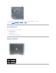
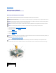
1 battery 2 cable 3 subwoofer 4 subwoofer cable connector 5. Connect the cable to the subwoofer connector. 6. Replace the battery in the battery bay.