Dell™ Vostro™ 420/220/220s Service Manual Troubleshooting Working on Your Computer Computer Cover Bezel Chassis Support Bracket PCI and PCI Express Cards Drives I/O Panel Fan Processor Heat Sink/Fan Assembly Memory Module(s) Power Supply Coin-Cell Battery System Board Processor System Setup Program Contacting Dell Notes, Notices, and Cautions NOTE: A NOTE indicates important information that helps you make better use of your computer.
Back to Contents Page Bezel Dell™ Vostro™ 420/220/220s Service Manual Removing the Bezel Replacing the Bezel CAUTION: Before working inside your computer, read the safety information that shipped with your computer. For additional safety best practices information, see the Regulatory Compliance Homepage at www.dell.com/regulatory_compliance. CAUTION: To guard against electrical shock, always unplug your computer from the electrical outlet before removing the cover.
. Perform the steps in the procedure After Working on Your Computer.
Back to Contents Page BIOS Dell™ Vostro™ 420/220/220s Service Manual Flashing the BIOS From a CD Flashing the BIOS From the Hard Drive If a BIOS-update program CD is provided with a new system board, flash the BIOS from the CD. If you do not have a BIOS-update program CD, see Flashing the BIOS From the Hard Drive. Flashing the BIOS From a CD NOTICE: Plug the AC adapter into a known good power source to prevent a loss of power. Failure to do so may cause system damage. 1. Turn on your computer. 2.
The file icon appears on your desktop and is titled the same as the downloaded BIOS update file. 8. Double-click the file icon on the desktop and follow the instructions on the screen.
Back to Contents Page Chassis Support Bracket Dell™ Vostro™ 420/220/220s Service Manual Removing the Chassis Support Bracket Replacing the Chassis Support Bracket CAUTION: Before working inside your computer, read the safety information that shipped with your computer. For additional safety best practices information, see the Regulatory Compliance Homepage at www.dell.com/regulatory_compliance.
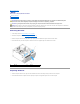
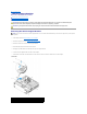
Replacing the Chassis Support Bracket 1. Holding the bracket at an angle, insert the tabs on one end of the bracket into the slots in the chassis. 2. While holding the bracket slightly raised, slide any cables as appropriate into the cable clip for storage. 3. Lower the other end of the bracket to engage the remaining tab. 4. Rotate the flange closed and replace and tighten the securing screw. 1 chassis support bracket 2 flange 3 screw 4 cable clip 5 slots (2) 6 tabs (2) 5.
Back to Contents Page PCI and PCI Express Cards Dell™ Vostro™ 420/220/220s Service Manual Removing a PCI or PCI Express Card Installing a PCI or PCI Express Card Configuring Your Computer After Removing or Installing a PCI or PCI Express Card CAUTION: Before working inside your computer, read the safety information that shipped with your computer. For additional safety best practices information, see the Regulatory Compliance Homepage at www.dell.com/regulatory_compliance.
5. Prepare the card for installation. See the documentation that came with the card for information on configuring the card, making internal connections, or otherwise customizing it for your computer. CAUTION: Some network adapters automatically start the computer when they are connected to a network. To guard against electrical shock, be sure to unplug your computer from its electrical outlet before installing any cards.
Type of Card Sound Card Installed 1. 2. 3. Network Card 1. 2. 3. Removed Enter the system setup program (see System Setup Program for instructions). Go to Integrated Peripherals, select Onboard Audio Controller, and then change the setting to Disabled. Connect the external audio devices to the sound card's connectors. 1. Enter the system setup program (see System Setup Program for instructions).
Back to Contents Page Coin-Cell Battery Dell™ Vostro™ 420/220/220s Service Manual Removing the Coin-Cell Battery Replacing the Coin-Cell Battery CAUTION: Before working inside your computer, read the safety information that shipped with your computer. For additional safety best practices information, see the Regulatory Compliance Homepage at www.dell.com/regulatory_compliance. CAUTION: A new battery can explode if it is incorrectly installed.
Back to Contents Page Contacting Dell Dell™ Vostro™ 420/220/220s Service Manual To contact Dell for sales, technical support, or customer service issues: 1. Visit support.dell.com. 2. Verify your country or region in the Choose a Country/Region drop-down menu at the bottom of the page. 3. Click Contact Us on the left side of the page. 4. Select the appropriate service or support link based on your need. 5. Choose the method of contacting Dell that is convenient for you.
Back to Contents Page Computer Cover Dell™ Vostro™ 420/220/220s Service Manual Removing the Computer Cover Replacing the Computer Cover CAUTION: Before working inside your computer, read the safety information that shipped with your computer. For additional safety best practices information, see the Regulatory Compliance Homepage at www.dell.com/regulatory_compliance. CAUTION: To guard against electrical shock, always unplug your computer from the electrical outlet before removing the cover.
frame beside the front bezel. 5. Ensure that the cover is seated and aligned correctly. 6. Replace and tighten the two thumbscrews that secure the computer cover. 7. Follow the procedure in After Working on Your Computer.
Back to Contents Page Processor Dell™ Vostro™ 420/220/220s Service Manual Removing the Processor Replacing the Processor CAUTION: Before working inside your computer, read the safety information that shipped with your computer. For additional safety best practices information, see the Regulatory Compliance Homepage at www.dell.com/regulatory_compliance. NOTICE: Do not perform the following steps unless you are familiar with hardware removal and replacement.
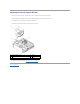
NOTICE: Socket pins are delicate. To avoid damage, ensure that the processor is aligned properly with the socket, and do not use excessive force when you install the processor. Be careful not to touch or bend the pins on the system board. 1 tab 2 processor cover 3 processor 4 processor socket 5 retention latch 6 release lever 7 processor pin-1 indicator 8 alignment notch 9 retention hook 10 alignment notch 2.
Back to Contents Page Drives Dell™ Vostro™ 420/220/220s Service Manual Hard Drives Media Card Reader Optical Drive Removing a Drive Bay Break-Away Metal Plate CAUTION: Before working inside your computer, read the safety information that shipped with your computer. For additional safety best practices information, see the Regulatory Compliance Homepage at www.dell.com/regulatory_compliance.
1 screws (4) 2 hard drive 3 power cable 4 data cable Vostro 220 1 screws (4) 2 hard drive 3 power cable 4 data cable 6. For the Vostro 220s: a. b. c. Raise and hold the hard-drive release latch. Slide the drive partway out of the bay, rotate the back of the drive upward until the drive is perpendicular to the drive cage, and guide the screws through the cutaway channels in the drive cage until you can lift the drive away from the computer.
1 cutaway channels (2) 2 hard-drive release latch 3 hard drive 4 screw guides (4) 5 power cable 6 data cable 7. If you are installing a replacement drive, skip to step 3 in Replacing or Adding a Hard Drive. If you are removing this drive permanently and the drive bay is to remain empty, proceed to step 8. 8. Disconnect the data cable from the system board (see System Board Components) and remove the cable from the computer. 9. Follow the procedure in After Working on Your Computer. 10.
1 cutaway channels (2) 2 hard-drive release latch 3 hard drive 4 screw guides (4) 5. For the Vostro 420 and Vostro 220: a. Slide the hard drive into the hard drive bay. b. Align the holes on the side of the hard drive with the holes in the drive cage, and install the screws to secure the hard drive in the bay.
1 screws (4) 2 hard drive 3 power cable 4 data cable 6. Connect the power and data cables to the back of the drive. NOTICE: The connectors are "keyed" for correct insertion; that is, a notch or a missing pin on one connector fits with a tab or a filled-in hole on the other connector. Align the cable connectors correctly before inserting them to avoid damage to the connectors. 7.
1 screws (2) 3 USB interface cable 4. 5. 2 media card reader Disconnect the USB cable from the back of the media card reader. For the Vostro 420 and Vostro 220, remove the two screws securing the device to the drive cage. For the Vostro 220s, lift the release latch that secures both the optical drive and the 3.5-inch device in their respective drive cages. 1 release latch 3 media card reader 6. 7. 2 optical drive bay Slide the device out through the front of the computer.
1 3.5-inch front-panel insert 10. For the Vostro 220s, push the release latch down to resecure the optical drive. 11. Install the cover for the empty bay onto the bezel: a. b. From the inside of the bezel, while holding the cover at an angle, insert the tab on one end of the cover into the slot on the corresponding end of the bezel opening. Lower the cover until it fits securely in the bezel opening. 1 tab 2 inside of bezel 3 cover for empty bay 4 slot in bezel opening 12.
1 inside of bezel 3 cover for empty bay 2 release latch 5. Remove the media card reader from its packaging. 6. For the Vostro 220s, install two screws on each side of the media card reader. 7. Gently slide the device into the bay from the front of the computer. 8. For the Vostro 420 and Vostro 220: 9. a. Align the screw holes in the device with the screw hole and slot in the drive cage. b. Replace and tighten the two screws to secure the device in the drive cage.
15. Enter the system setup program (see System Setup Program for instructions) and update the drive settings. Optical Drive CAUTION: Before working inside your computer, read the safety information that shipped with your computer. For additional safety best practices information, see the Regulatory Compliance Homepage at www.dell.com/regulatory_compliance. CAUTION: To guard against electrical shock, always unplug your computer from the electrical outlet before removing the cover.
1 screws (2) 2 5.25-inch front-panel insert NOTE: To comply with FCC regulations, install the 5.25-inch front-panel insert whenever an optical drive is permanently removed from the computer. 10. Replace the bezel (see Replacing the Bezel). 11. Follow the procedure in After Working on Your Computer. 12. Enter the system setup program (see System Setup Program for instructions) and update the drive settings. Replacing or Adding an Optical Drive 1.
1 screws (2) 2 screw holes 3 optical drive 4 data cable 5 power cable 10. Replace the bezel (see Replacing the Bezel). 11. Follow the procedure in After Working on Your Computer. 12. See the documentation that came with the drive for instructions on installing any software required for drive operation. 13. Enter the system setup program (see System Setup Program for instructions) and update the drive settings.
1 5.25-inch bay metal plate (for empty optical-drive bay NOTE: Store 5.25-inch metal plates for reuse should you decide to permanently remove an optical drive in the future. Only the break-away metal plates for the optical drive bays have screw holes for reuse. An empty optical-drive bay opening must be covered by a metal plate (front-panel insert) to retain FCC ratings. Vostro 220s To remove the 3.
Back to Contents Page Fan Dell™ Vostro™ 420/220/220s Service Manual Removing the Chassis Fan Replacing the Chassis Fan CAUTION: Before working inside your computer, read the safety information that shipped with your computer. For additional safety best practices information, see the Regulatory Compliance Homepage at www.dell.com/regulatory_compliance.
1 chassis fan 3 screws (4) 2 system board power connector Vostro 220s 1 system board power connector 3 screw 2 chassis fan Replacing the Chassis Fan 1. For the Vostro 220s: a. Lower the fan into the chassis such that the screw hole in the fan is offset and slightly forward of the screw hole in the fan mount on the chassis. b. Press the fan into the side of the chassis, and then slide it toward the back of the computer until it sets against the stops. c. Proceed to step 3.
2. While holding the chassis fan in place, align the screw hole(s) and install the screw(s) that secure the fan to the chassis. 3. Attach the fan cable to the system board (see System Board Components). 4. Follow the procedure in After Working on Your Computer.
Back to Contents Page Processor Heat Sink/Fan Assembly Dell™ Vostro™ 420/220/220s Service Manual Removing the Processor Heat Sink/Fan Assembly Replacing the Processor Heat Sink/Fan Assembly CAUTION: Before working inside your computer, read the safety information that shipped with your computer. For additional safety best practices information, see the Regulatory Compliance Homepage at www.dell.com/regulatory_compliance.
Replacing the Processor Heat Sink/Fan Assembly NOTICE: Unless a new heat sink is required for the new processor, reuse the original heat sink/fan assembly when you replace the processor. 1. Apply thermal solution to the heat sink as needed. 2. Align the four captive screws on the heat sink/fan assembly with the holes and rubber bushings on the system board.
Back to Contents Page I/O Panel Dell™ Vostro™ 420/220/220s Service Manual Removing the I/O Panel Replacing the I/O Panel CAUTION: Before working inside your computer, read the safety information that shipped with your computer. For additional safety best practices information, see the Regulatory Compliance Homepage at www.dell.com/regulatory_compliance. CAUTION: To guard against electrical shock, always unplug your computer from the electrical outlet before removing the cover.
1 front-panel opening 3 screw 2 I/O panel and cables Replacing the I/O Panel NOTICE: Take care not to damage the cable connectors and the cable routing clip(s) (if present) when sliding the I/O panel into the computer. 1. Route the I/O panel cables into the chassis through the I/O panel opening, and guide them through the various holes and bays. 2. Slide the I/O panel cables into the cable clip(s) (if present). 3. Replace and tighten the screw that secures the I/O panel. 4.
Back to Contents Page Memory Module(s) Dell™ Vostro™ 420/220/220s Service Manual Removing Memory Modules Replacing or Adding a Memory Module CAUTION: Before working inside your computer, read the safety information that shipped with your computer. For additional safety best practices information, see the Regulatory Compliance Homepage at www.dell.com/regulatory_compliance. Removing Memory Modules 1. Follow the procedures in Before Working on Your Computer. 2.
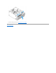
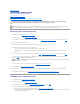
and DIMM_2 1. and DIMM_4 Align the notch on the bottom of the module with the crossbar in the connector. . 1 cutouts (2) 2 memory module 3 notch 4 crossbar NOTICE: To avoid damage to the memory module, press the module straight down into the connector while you apply equal force to each end of the module. 2. Insert the module into the connector until the module snaps into position. If you insert the module correctly, the securing clips snap into the cutouts at each end of the module. 3.
Back to Contents Page Power Supply Dell™ Vostro™ 420/220/220s Service Manual Removing the Power Supply Replacing the Power Supply DC Power Supply Connectors DC Power Supply Connector Pin Assignments CAUTION: Before working inside your computer, read the safety information that shipped with your computer. For additional safety best practices information, see the Regulatory Compliance Homepage at www.dell.com/regulatory_compliance.
1. Set the replacement power supply into place. 2. Replace and tighten the screws that secure the power supply to the back of the computer chassis. CAUTION: Failure to replace and tighten all screws may cause electrical shock as these screws are a key part of the grounding system. NOTICE: Route the DC power cables as you insert them into the routing clips (if present). The cables must be properly routed to prevent the cables from being damaged. 3.
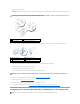
Vostro 220 Vostro 220s DC Power Supply Connector Pin Assignments
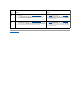
DC Power Connector P1 Pin Number Signal name Wire Color Wire Size 1 3.3 V Orange 20 AWG 2 3.3 V Orange 20 AWG 3 RTN Black 20 AWG 4 5V Red 20 AWG 5 RTN Black 20 AWG 6 5V Red 20 AWG 7 RTN Black 20 AWG 8 POK Gray 22 AWG 9 5 V AUX Purple 20 AWG 10 +12 V Yellow 20 AWG 11 +12 V Yellow 20 AWG 12 3.3 V Orange 20 AWG 13 3.
2 GND Black 3 +5 VDC Red 4 GND Black 5 +12 VBDC White DC Power Connector P9 Pin Number Signal Name 22-AWG Wire 1 +5 VDC Red 2 GND Black 3 GND Black 4 +12 VADC Yellow DC Power Connector P10 Pin Number Signal Name 22-AWG Wire 1 +12 VDC Yellow 2 +12 VDC Yellow 3 +12 VDC Yellow 4 GND Black 5 GND Black 6 GND Black Back to Contents Page
Back to Contents Page System Board Dell™ Vostro™ 420/220/220s Service Manual Remove the System Board Replacing a System Board CAUTION: Before working inside your computer, read the safety information that shipped with your computer. For additional safety best practices information, see the Regulatory Compliance Homepage at www.dell.com/regulatory_compliance.
1 system board 2 screws (9) Replacing a System Board 1. Align the holes of the system board with the screw holes in the chassis, ensuring that the back panel connectors are properly aligned in the openings on the back of the chassis. 2. Replace the screws that secure the system board to the chassis. Avoid over-tightening the screws. CAUTION: Failure to replace and tighten all screws properly may not provide adequate grounding of the system board and result in system failures. 3.
a. Install the processor heat sink/fan assembly (see Replacing the Processor Heat Sink/Fan Assembly). 5. Connect the power supply cables to the system board (see System Board Components for connector locations). 6. Connect all front panel cables to the system board (see System Board Components for connector locations). 7. Connect all the data cables from the drives to the system board (see System Board Components for connector locations). 8.
Back to Contents Page System Setup Program Dell™ Vostro™ 420/220/220s Service Manual Overview Entering the System Setup Program System Setup Program Screens System Setup Program Options Boot Sequence Clearing Forgotten Passwords Clearing CMOS Settings BIOS Overview Use the system setup program as follows: l To change the system configuration information after you add, change, or remove any hardware in your computer l To set or change a user-selectable option such as the user password l To read the cu
Key Functions — This field appears below the Option Field and lists keys and their functions within the active system setup program field. System Setup Program Options NOTE: Depending on your computer and installed devices, the items listed in this section may not appear, or may not appear exactly as listed. System Info System Info Lists system information such as the computer name, and other system-specific information. BIOS Info Shows the BIOS version number and date information.
This feature allows you to change the boot sequence for devices. Option Settings l Diskette Drive — The computer attempts to boot from a floppy drive (if installed). If the floppy disk in the drive is not bootable, if no floppy disk is in the drive, or if there is no floppy drive installed in the computer, the computer generates an error message. l Hard Drive — The computer attempts to boot from the primary hard drive. If no operating system is on the drive, the computer generates an error message.
4. Remove the 2-pin jumper plug from pins 2 and 3 and fix it on pins 1 and 2. 5. Wait for approximately five seconds to clear the password. 6. Remove the 2-pin jumper plug from pins 1 and 2 and replace it on pins 2 and 3 to enable the password feature. 7. Follow the procedure in After Working on Your Computer. Clearing CMOS Settings CAUTION: Before working inside your computer, read the safety information that shipped with your computer.
8. Double-click the file icon on the desktop and follow the instructions on the screen.
Back to Contents Page Dell™ Vostro™ 420/220/220s Service Manual NOTE: A NOTE indicates important information that helps you make better use of your computer. NOTICE: A NOTICE indicates either potential damage to hardware or loss of data and tells you how to avoid the problem. CAUTION: A CAUTION indicates potential for property damage, personal injury, or death. If you purchased a Dell™ n Series computer, any references in this document to Microsoft® Windows® operating systems are not applicable.
Back to Contents Page Troubleshooting Dell™ Vostro™ 420/220/220s Service Manual Tools Dell Diagnostics Solving Problems Dell Technical Update Service Dell Support Utility Tools Power Lights CAUTION: Before working inside your computer, read the safety information that shipped with your computer. For additional safety best practices information, see the Regulatory Compliance Homepage at www.dell.com/regulatory_compliance.
2 No memory modules are detected. l l l 3 Possible system board failure. 4 RAM Read/Write failure. Contact Dell (see Contacting Dell). l l l 5 Real time clock failure. Possible battery or system board failure. 6 Video BIOS Test Failure. If two or more memory modules are installed, remove the modules (see Replacing or Adding a Memory Module), and then reinstall one module and restart the computer.
4. In the Hardware Troubleshooter list, select the option that best describes the problem and click Next to follow the remaining troubleshooting steps. ® Windows Vista : 1. Click the Windows Vista start button , and click Help and Support. 2. Type hardware troubleshooter in the search field and press to start the search. 3. In the search results, select the option that best describes the problem and follow the remaining troubleshooting steps.
9. Close the Main Menu window to exit the Dell Diagnostics and restart the computer. Starting the Dell Diagnostics From the Drivers and Utilities Disc Before running the Dell Diagnostics, enter the system setup program (see System Setup Program) to review your computer's configuration information, and ensure that the device you want to test is displayed in the system setup program and is active. 1. Insert the Drivers and Utilities disc into the optical drive. 2. Restart your computer. 3.
After Test System is selected, the following menu appears: Option Function Express Test Performs a quick test of devices in the system. This typically can take 10 to 20 minutes. NOTE: The Express Test requires no interaction on your part. Run Express Test first to increase the possibility of tracing a problem quickly. Extended Test Performs a thorough check of devices in the system. This typically can take an hour or more.
Drive Problems CAUTION: Before you begin any of the procedures in this section, follow the safety instructions that shipped with your computer. For additional safety best practices information, see the Regulatory Compliance Homepage at www.dell.com/regulatory_compliance. Ensure that Microsoft® Windows® Recognizes the drive — Windows XP: l Click Start and click My Computer. Windows Vista®: l Click the Windows Vista Start button and click Computer.
4. Click Scan for and attempt recovery of bad sectors and click Start. Windows Vista: 1. 2. 3. Click Start and click Computer. Right-click Local Disk C:. Click Properties® Tools® Check Now. The User Account Control window may appear. If you are an administrator on the computer, click Continue; otherwise, contact your administrator to continue the desired action. 4. Follow the instructions on the screen.
1. 2. Click Start and click Control Panel. Under Pick a Category, click Performance and Maintenance® System® System Properties ® Hardware® Device Manager. Windows Vista: 1. 2. Click Start ® Control Panel® Hardware and Sound. Click Device Manager. If your IEEE 1394 device is listed, Windows recognizes the device. If you have problems with a Dell IEEE 1394 device — Contact Dell (see Contacting Dell).
A program crashes repeatedly NOTE: Most software includes installation instructions in its documentation or on a CD or DVD. Check the software documentation — If necessary, uninstall and then reinstall the program. A program is designed for an earlier Windows operating system Run the Program Compatibility Wizard — Windows XP: The Program Compatibility Wizard configures a program so that it runs in an environment similar to non-XP operating system environments. 1. 2.
l l Ensure that the memory you are using is supported by your computer. For more information about the type of memory supported by your computer, see "Specifications" in the Setup and Quick Reference Guide. Run the Dell Diagnostics (see Dell Diagnostics). Mouse Problems CAUTION: Before you begin any of the procedures in this section, follow the safety instructions that shipped with your computer. For additional safety best practices information, see the Regulatory Compliance Homepage at www.dell.
CAUTION: Before you begin any of the procedures in this section, follow the safety instructions that shipped with your computer. For additional safety best practices information, see the Regulatory Compliance Homepage at www.dell.com/regulatory_compliance. If the power light is blue and the computer is not responding — See Power Lights. If the power light is blinking blue — The computer is in standby mode. Press a key on the keyboard, move the mouse, or press the power button to resume normal operation.
4. Adjust the settings, as needed. Reinstall the printer driver — See the printer documentation for information on reinstalling the printer driver. Scanner Problems CAUTION: Before you begin any of the procedures in this section, follow the safety instructions that shipped with your computer. For additional safety best practices information, see the Regulatory Compliance Homepage at www.dell.com/regulatory_compliance.
Test the electrical outlet — Ensure that the electrical outlet is working by testing it with another device, such as a lamp. Eliminate possible interference — Turn off nearby fans, fluorescent lights, or halogen lamps to check for interference. Run the speaker diagnostics Reinstall the sound driver Run the Hardware Troubleshooter — See Hardware Troubleshooter.
Move the subwoofer away from the monitor — If your speaker system includes a subwoofer, ensure that the subwoofer is positioned at least 60 centimeters (2 feet) away from the monitor. Move the monitor away from external power sources — Fans, fluorescent lights, halogen lamps, and other electrical devices can cause the screen image to appear shaky. Turn off nearby devices to check for interference.
2. Ensure that the Show icon on the taskbar option is checked. NOTE: If the Dell Support Utility is not available from the Start menu, go to support.dell.com and download the software. The Dell Support Utility is customized for your computing environment. The icon in the taskbar functions differently when you click, double-click, or right-click the icon. Clicking the Dell Support Icon Click or right-click the icon to perform the following tasks: l Check your computing environment.
Back to Contents Page Working on Your Computer Dell™ Vostro™ 420/220/220s Service Manual Recommended Tools Before Working on Your Computer Inside View of Your Computer System Board Components After Working on Your Computer This document provides procedures for removing and installing the components in your computer. Unless otherwise noted, each procedure assumes that: l You have performed the steps in Working on Your Computer. l You have read the safety information that shipped with your computer.
2. Ensure that the computer and all attached devices are turned off. If your computer and attached devices did not automatically turn off when you shut down your operating system, press and hold the power button for about 4 seconds to turn them off. Inside View of Your Computer Vostro™ 420 1 power supply 2 5.25-inch drive bays (3) 3 media card reader (optional) 4 I/O panel 5 3.5-inch hard drive bays (4) 6 chassis fan Vostro 220 1 power supply 2 5.
1 power supply 2 chassis fan 3 optical drive 4 media card reader (optional) 5 I/O panel 6 3.5-inch hard drive bays (2) ` System Board Components Vostro 420 1 power connector (PWR2) 2 processor heat sink/fan assembly power 3 memory module connectors (4) (DIMM_1, DIMM_2, DIMM_3, DIMM_4) 4 main power connector (PWR1) 5 battery socket 6 serial ATA 5.
22 PCI Express x1 connector (PCIE_X1 2) 23 PCI Express x16 connector (PCIE_x16) 24 PCI Express x1 connector (PCIE_X1 1) 25 audio connectors 26 one LAN and two USB ports 27 USB ports (2) 28 USB ports (2) and ESATA connector 29 chassis fan connector 30 Display Port 31 video (VGA) and parallel ports 32 PS/2 mouse and keyboard connectors Vostro 220 1 power connector (PWR2) 2 processor heat sink/fan assembly power 3 memory module connectors (2) 4 main power connector (PWR1) 5 serial ATA driv
1 power connector (PWR2) 2 processor heat sink/fan assembly power 3 memory module connectors (2) 4 main power connector (PWR1) 5 serial ATA drive connector (SATA2) 6 serial ATA drive connector (SATA1) 7 serial ATA drive connector (SATA3) 8 serial ATA drive connector (SATA0) 9 battery socket 10 front I/O panel connector 11 USB1 system board connector (from front I/O panel) 12 USB2 system board connector (from front I/O panel) 13 CMOS jumper (CLEAR CMOS) 14 USB3 system board connector 1