Dell PowerEdge M620 Systems Owner's Manual Regulatory Model: HHB Regulatory Type: HHB003
Notes, Cautions, and Warnings NOTE: A NOTE indicates important information that helps you make better use of your computer. CAUTION: A CAUTION indicates either potential damage to hardware or loss of data and tells you how to avoid the problem. WARNING: A WARNING indicates a potential for property damage, personal injury, or death. © 2013 Dell Inc. All Rights Reserved.
Contents 1 About Your System......................................................................................................................7 Front-Panel Features And Indicators....................................................................................................................... 7 Using USB Diskette or USB DVD/CD Drives............................................................................................................. 7 Hard-Drive/SSD Indicator Patterns.......................
Recommended Tools.............................................................................................................................................. 25 Removing And Installing A Blade........................................................................................................................... 25 Removing The Blade........................................................................................................................................ 25 Installing The Blade.............
Installing The Hard-Drive/SSD Backplane.......................................................................................................53 System Board..........................................................................................................................................................53 Removing The System Board........................................................................................................................... 53 Installing The System Board...................
Alert Messages.....................................................................................................................................................142 9 Getting Help..............................................................................................................................143 Contacting Dell.....................................................................................................................................................
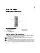
1 About Your System Front-Panel Features And Indicators Figure 1. Front-Panel Features and Indicators 1. blade handle release button 2. hard drives (2) 3. status/identification indicator 4. USB connectors (2) 5. blade power button Using USB Diskette or USB DVD/CD Drives The blade has USB ports on the front which allow you to connect a USB diskette drive, USB flash drive, USB DVD/CD drive, keyboard, or mouse. The USB drives can be used to configure the blade.
Hard-Drive/SSD Indicator Patterns The hard-drive/SSD indicators display different patterns as drive events occur in the system. NOTE: The blade must have a hard drive/SSD or a hard-drive blank installed in each drive bay. Figure 2. Hard-Drive/SSD Indicators 1. drive activity indicator (green) 2. drive status indicator (green and amber) NOTE: If the drive is in Advanced Host Controller Interface (AHCI) mode, the status LED (on the right side) does not function and remains off.
Other Information You May Need WARNING: See the safety and regulatory information that shipped with your system. Warranty information may be included within this document or as a separate document. • The Getting Started Guide provides an overview of system features, setting up your system, and technical specifications. • The Rack Installation Instructions included with your rack solution describes how to install your system into a rack.
Using The System Setup And Boot Manager 2 System Setup enables you to manage your system hardware and specify BIOS-level options. The following keystrokes provide access to system features during startup: Keystroke Description Enters the System Setup. Enters System Services, which opens the Dell Lifecycle Controller 2 (LC2). The Dell LC2 allows you to access utilities such as embedded system diagnostics. For more information, see the Dell LC2 documentation.
NOTE: Operating systems must be UEFI-compatible to be installed from the UEFI boot mode. DOS and 32-bit operating systems do not support UEFI and can only be installed from the BIOS boot mode. NOTE: For the latest information on supported operating systems, see dell.com/ossupport. Entering System Setup 1. Turn on or restart your system. 2.
Menu Item Description Device Settings This option is used to view and configure device settings. System BIOS Screen NOTE: The options for System Setup change based on the system configuration. NOTE: System Setup defaults are listed under their respective options in the following sections, where applicable. Menu Item Description iDRAC Settings This option is used to view and configure iDRAC settings. Device Settings This option is used to view and configure device settings.
Memory Settings Screen Menu Item Description System Memory Size Displays the amount of memory installed in the system. System Memory Type Displays the type of memory installed in the system. System Memory Speed Displays the system memory speed. System Memory Voltage Displays the system memory voltage. Video Memory Displays the amount of video memory. System Memory Testing Specifies whether system memory tests are run during system boot. Options are Enabled and Disabled.
Menu Item Description Virtualization Technology Allows you enable or disable the additional hardware capabilities provided for virtualization. By default, the Virtualization Technology option is set to Enabled. Adjacent Cache Line Prefetch Allows you to optimize the system for applications that require high utilization of sequential memory access. By default, the Adjacent Cache Line Prefetch option is set to Enabled.
Menu Item Description CAUTION: Switching the boot mode may prevent the system from booting if the operating system is not installed in the same boot mode. If the operating system supports UEFI, you can set this option to UEFI. Setting this field to BIOS allows compatibility with non-UEFI operating systems. By default, the Boot Mode option is set to BIOS. NOTE: Setting this field to UEFI disables BIOS Boot Settings menu. Setting this field to BIOS disables the UEFI Boot Settings menu.
Menu Item Description OS Watchdog Timer Allows you to enable or disable the OS watchdog timer. When this field is enabled, the operating system initializes the timer and the OS watchdog timer helps in recovering the operating system. By default, the OS Watchdog Timer option is set to Disabled. Embedded Video Controller Allows you to enable or disable the Embedded Video Controller. By default, the embedded video controller is Enabled.
System Profile Settings Screen Menu Item Description System Profile Allows you to set the system profile. If you set the System Profile option to a mode other than Custom, the BIOS automatically sets the rest of the options. You can only change the rest of the options if the mode is set to Custom. By default, the System Profile option is set to Performance Per Watt Optimized (DAPC). DAPC is Dell Active Power Controller.
Menu Item Description System Password Allows you to set the system password. This option is read-only if the password jumper is not installed in the system. Setup Password Allows you to set the setup password. This option is read-only if the password jumper is not installed in the system. Password Status Allows you to lock the system password. By default, the Password Status option is set to Unlocked. TPM Security Allows you to control the reporting mode of the Trusted Platform Module (TPM).
Menu Item Description Report Keyboard Errors Allows you to set whether keyboard-related error messages are reported during system boot. By default, the Report Keyboard Errors field is set to Report. F1/F2 Prompt on Error Allows you to enable or disable the F1/F2 prompt on error. By default, F1/F2 Prompt on Error is set to Enabled. In-System Characterization This field enables or disables In-System Characterization. By default, In-System Characterization is set to Enabled.
– The following special characters are allowed: space, (”), (+), (,), (-), (.), (/), (;), ([), (\), (]), (`). A message prompts you to re-enter the system password. 6. Re-enter the system password that you entered earlier and click OK. 7. Select Setup Password, enter your system password and press or . A message prompts you to re-enter the setup password. 8. Re-enter the setup password that you entered earlier and click OK. 9. Press to save the changes.
Operating With A Setup Password Enabled If Setup Password is Enabled, enter the correct setup password before modifying most of the System Setup options. If you do not enter the correct password in three attempts, the system displays the message Incorrect Password! Number of unsuccessful password attempts: System Halted! Must power down. Even after you shut down and restart the system, the error message is displayed until the correct password is entered.
NOTE: For most of the options, any changes that you make are recorded but do not take effect until you restart the system. Boot Manager Screen Menu Item Description Continue Normal Boot The system attempts to boot to devices starting with the first item in the boot order. If the boot attempt fails, the system continues with the next item in the boot order until the boot is successful or no more boot options are found.
• Configure, enable, or disable the iDRAC local area network through the dedicated iDRAC Enterprise card port or the embedded NIC • Enable or disable IPMI over LAN • Enable a LAN Platform Event Trap (PET) destination • Attach or detach the Virtual Media devices For more information on using iDRAC7, see the iDRAC7 User's Guide, at dell.com/supoort/manuals. Entering The iDRAC Settings Utility 1. Turn on or restart the managed system. 2. Press during Power-on Self-test (POST). 3.
Installing Blade Components 3 Recommended Tools You may need the following items to perform the procedures in this section: • #1 and #2 Phillips screwdrivers • T8 and T10 Torx drivers • Wrist grounding strap Removing And Installing A Blade CAUTION: Many repairs may only be done by a certified service technician. You should only perform troubleshooting and simple repairs as authorized in your product documentation, or as directed by the online or telephone service and support team.
Figure 3. Removing or Installing the Blade 1. blade handle 2. release button 3. blade 4. guide rail on enclosure 5. guide rail on blade (or blade blank) Installing The Blade 1. If you are installing a new blade, remove the plastic cover from the I/O connector(s) and save for future use. 2. Orient the blade so that the handle is on the left side of the blade. 3.
Opening And Closing The Blade Opening The Blade CAUTION: Many repairs may only be done by a certified service technician. You should only perform troubleshooting and simple repairs as authorized in your product documentation, or as directed by the online or telephone service and support team. Damage due to servicing that is not authorized by Dell is not covered by your warranty. Read and follow the safety instructions that came with the product.
Closing The Blade 1. Ensure that no tools or parts are left inside the blade. 2. Align the notches in the edges of the chassis with the cover alignment pins on the inner sides of the cover. 3. Lower the cover onto the chassis. 4. Slide the cover until it clicks into position. A properly seated cover is flush with the surface of the chassis. Inside The Blade Figure 5. Inside the Blade 1. 2. 3. 4. 5. 6. 7.
Cooling Shroud The cooling shroud covers the memory modules and directs air flow in the system. Removing The Cooling Shroud CAUTION: Many repairs may only be done by a certified service technician. You should only perform troubleshooting and simple repairs as authorized in your product documentation, or as directed by the online or telephone service and support team. Damage due to servicing that is not authorized by Dell is not covered by your warranty.
Installing The Cooling Shroud CAUTION: Many repairs may only be done by a certified service technician. You should only perform troubleshooting and simple repairs as authorized in your product documentation, or as directed by the online or telephone service and support team. Damage due to servicing that is not authorized by Dell is not covered by your warranty. Read and follow the safety instructions that came with the product. 1.
DIMM Type LRDIMM DIMMs Populated/ Channel Operating Frequency (in MT/s) Maximum DIMM Rank/ Channel 1.5 V 1.35 V 1 1333 and 1066 1333 and 1066 Quad rank 2 1333 and 1066 1333 and 1066 Quad rank 3 1066 1066 Quad rank Figure 7.
General Memory Module Installation Guidelines NOTE: Memory configurations that fail to observe these guidelines can prevent your system from starting and producing any video output, hanging during memory configuration, or operating with reduced memory. This system supports Flexible Memory Configuration, enabling the system to be configured and run in any valid chipset architectural configuration. The following are the recommended guidelines for best performance: • UDIMMs and RDIMMs must not be mixed.
The following sections provide additional slot population guidelines for each mode. Advanced ECC (Lockstep) Advanced ECC mode extends SDDC from x4 DRAM based DIMMs to both x4 and x8 DRAMs. This protects against single DRAM chip failures during normal operation. Memory installation guidelines: • Memory modules must be identical in size, speed, and technology.
Table 1.
Table 2.
System Capacity (in GB) DIMM Size (in GB) Number of DIMMs Organization and Speed DIMM Slot Population 384 16 24 2R x4, 1333 MT/s A1, A2, A3, A4, A5, A6, A7, A8, A9, A10, A11, A12, B1, B2, B3, B4, B5, B6, B7, B8, B9, B10, B11, B12 512 32 16 4R x4, 1333 MT/s A1, A2, A3, A4, A5, A6, A7, A8, B1, B2, B3, B4, B5, B6, B7, B8 768 32 24 4R x4, 1333 MT/s A1, A2, A3, A4, A5, A6, A7, A8, A9, A10, A11, A12, B1, B2, B3, B4, B5, B6, B7, B8, B9, B10, B11, B12 (LRDIMMs only) Removing Memory Modules WARN
Figure 8. Installing and Removing a Memory Module or Memory Module Blank 1. memory module or memory blank 2. edge connector 3. ejectors (2) 4. socket 5. alignment key Installing Memory Modules WARNING: The memory modules are hot to the touch for some time after the system has been powered down. Allow time for the memory modules to cool before handling them. Handle the memory modules by the card edges and avoid touching the components or metallic contacts on the memory module.
6. Align the memory module's edge connector with the alignment key on the memory module socket, and insert the memory module in the socket. NOTE: The memory module socket has an alignment key that allows you to install the memory module in the socket in only one way. 7. Press down on the memory module with your thumbs to lock the memory module into the socket.
5. Close the retention latch. 6. Close the blade. 7. Install the blade in the enclosure. Figure 9. Installing and Removing a Mezzanine Card 1. 2. 3. 4. mezzanine cards (2) Fabric B mezzanine card slot Fabric C mezzanine card slot retention latch Installing A Mezzanine Card CAUTION: Many repairs may only be done by a certified service technician.
6. Lower the card into place until it is fully seated and the plastic clip on the outer edge of the card fits over the side of the blade chassis. 7. Close the retention latch to secure the mezzanine card. 8. Close the blade. 9. Install the blade in the enclosure. Management Riser Card The management riser card provides two SD card slots and a USB interface dedicated for the embedded hypervisor.
Figure 10. Replacing the SD Card 1. 2. 3. 4. SD card management riser card USB connector SD card slots Internal USB Key The blade provides an internal USB connector for a USB flash memory key. The USB memory key can be used as a boot device, security key, or mass storage device. To use the internal USB connector, the Internal USB Port option must be enabled in the Integrated Devices screen of the System Setup.
7. Install the blade in the enclosure. 8. Enter the System Setup and verify that the USB key is detected by the system. Figure 11. Replacing the USB Memory Key 1. USB memory key connector 2. USB memory key SD vFlash Card Replacing The SD vFlash Card 1. Remove the blade from the enclosure. 2. If installed, remove the SD vFlash card from the card slot. NOTE: The SD vFlash card slot is near the Fabric B mezzanine card slot at the back corner of the blade. 3.
Network Daughter Card/LOM Riser Card Removing The Network Daughter Card/LOM Riser Card CAUTION: Many repairs may only be done by a certified service technician. You should only perform troubleshooting and simple repairs as authorized in your product documentation, or as directed by the online or telephone service and support team. Damage due to servicing that is not authorized by Dell is not covered by your warranty. Read and follow the safety instructions that came with the product. 1.
Installing The Network Daughter Card/LOM Riser Card CAUTION: Many repairs may only be done by a certified service technician. You should only perform troubleshooting and simple repairs as authorized in your product documentation, or as directed by the online or telephone service and support team. Damage due to servicing that is not authorized by Dell is not covered by your warranty. Read and follow the safety instructions that came with the product. 1. Remove the blade from the enclosure. 2.
Figure 14. Installing and Removing a Heat Sink 1. screws (4) 2. heat sink 6. Use a clean, lint-free cloth to remove any thermal grease from the surface of the processor shield. CAUTION: The processor is held in its socket under strong pressure. Be aware that the release lever can spring up suddenly if not firmly grasped. 7. Position your thumb firmly over the socket-release lever near the label marked OPEN 1st and release the lever from the locked position by pushing down and out from under the tab. 8.
Figure 15. Processor Shield Opening and Closing Lever Sequence 1. OPEN 1st label 2. open first lever 3. processor 9. 4. close first lever 5. CLOSE 1st label Hold the tab on the processor shield and rotate it upward and out of the way. 10. If applicable, remove the socket protective cap from the processor shield. To remove the socket protective cap, push the cap from the inside of the processor shield and move it away from the socket pins.
Figure 16. Installing and Removing a Processor 1. 2. 3. 4. 5. socket-release lever 2 pin-1 corner of processor tabs (2) processor shield socket protective cap 6. socket-release lever 1 7. pin-1 corner on system board 8.
Installing A Processor CAUTION: Many repairs may only be done by a certified service technician. You should only perform troubleshooting and simple repairs as authorized in your product documentation, or as directed by the online or telephone service and support team. Damage due to servicing that is not authorized by Dell is not covered by your warranty. Read and follow the safety instructions that came with the product. NOTE: If you are installing just one processor, it must be installed in socket CPU1. 1.
c) Tighten the four screws to secure the heat sink to the blade board. NOTE: Do not over-tighten the heat sink retention screws when installing the heat sink. To prevent overtightening, tighten the retention screw until resistance is felt, and stop once the screw is seated. The screw tension should be no more than 6 in-lb (6.9 kg-cm). 7. Install the cooling shroud. 8. Close the blade. 9. Install the blade in the enclosure.
Figure 17. Removing and Installing a Hard Drive/SSD 1. 2. 3. 4. release button hard drive/SSD hard-drive/SSD connector (on backplane) hard-drive/SSD carrier handle Installing A Hard Drive/SSD CAUTION: When a replacement hot-swappable hard drive/SSD is installed and the blade is powered on, the drive automatically begins to rebuild. Make absolutely sure that the replacement hard drive/SSD is blank or contains data that you wish to have over-written.
CAUTION: If you need to power off the blade to service a hard drive/SSD, wait 30 seconds after the blade’s power indicator turns off before removing the hard drive/SSD. Otherwise, the hard drive/SSD may not be recognized after it is reinstalled and the blade is powered on again. Configuring The Boot Drive The drive or device from which the system boots is determined by the boot order specified in the System Setup. Removing A Hard Drive/SSD From A Hard-Drive/SSD Carrier 1.
Hard-Drive/SSD Backplane Removing The Hard-Drive/SSD Backplane CAUTION: Many repairs may only be done by a certified service technician. You should only perform troubleshooting and simple repairs as authorized in your product documentation, or as directed by the online or telephone service and support team. Damage due to servicing that is not authorized by Dell is not covered by your warranty. Read and follow the safety instructions that came with the product. 1. Remove the blade from the enclosure. 2.
1. guide pins (3) 2. guides (3) 3. hard-drive/SSD backplane 4. hard-drive/SSD connectors (2) 5. hard-drive backplane/SSD connector Installing The Hard-Drive/SSD Backplane 1. Open the blade. 2. Align the guides on the hard-drive/SSD backplane with the guide pins on the system board. 3. Press down the backplane until the connectors on the backplane and the system board are fully engaged. 4. Install the hard drives/SSDs in their original locations. 5. Close the blade. 6.
Figure 20. Removing and Installing the System Board 1. I/O connector cover 2. retention latch 3. system board 4. tabs on system chassis 5. slots in system board tray Installing The System Board 1. 2.
6. Reinstall the cooling shroud. 7. Close the blade. 8. Remove the plastic I/O connector covers from the back of the blade. 9. Install the blade in the enclosure. 10. Import your new or existing iDRAC Enterprise license. For more information, see the iDRAC7 User's Guide at support.dell.com/manuals. NVRAM Backup Battery Replacing The NVRAM Backup Battery WARNING: There is a danger of a new battery exploding if it is incorrectly installed.
Figure 21. Replacing the NVRAM Backup Battery 1. positive side of battery 2. negative side of battery connector Storage Controller Card Your system includes a dedicated expansion-card slot on the blade system board for the storage controller card that provides the integrated storage subsystem for your system’s hard drives. The storage controller card supports SAS and SATA hard drives. NOTE: The storage controller card is located underneath the drive bays.
Figure 22. Removing and Installing the PCIe Extender/Storage Controller Card 1. 2. 3. 4. PCIe extender/storage controller card screws (2) tab connector Installing The PCIe Extender Card/Storage Controller Card 1. Holding by its edges, position the PCIe extender/storage controller card so that the card-connector aligns with the system board connector. 2. Adjust the other end of the card so that the card edge is secured under the two tabs on the plastic bracket. 3.
Troubleshooting Your System 4 Safety First—For You and Your System CAUTION: Many repairs may only be done by a certified service technician. You should only perform troubleshooting and simple repairs as authorized in your product documentation, or as directed by the online or telephone service and support team. Damage due to servicing that is not authorized by Dell is not covered by your warranty. Read and follow the safety instructions that came with the product.
Troubleshooting Hard Drives CAUTION: Many repairs may only be done by a certified service technician. You should only perform troubleshooting and simple repairs as authorized in your product documentation, or as directed by the online or telephone service and support team. Damage due to servicing that is not authorized by Dell is not covered by your warranty. Read and follow the safety instructions that came with the product. CAUTION: This troubleshooting procedure can destroy data stored on the hard drive.
Troubleshooting An Internal SD Card CAUTION: Many repairs may only be done by a certified service technician. You should only perform troubleshooting and simple repairs as authorized in your product documentation, or as directed by the online or telephone service and support team. Damage due to servicing that is not authorized by Dell is not covered by your warranty. Read and follow the safety instructions that came with the product. 1.
4. If there is a still a problem with the blade, remove and reinstall the blade in the enclosure. 5. Turn on the blade. 6. Run the appropriate diagnostic test. For more information, see Using System Diagnostics. If the tests fail, see Getting Help. Troubleshooting The NVRAM Backup Battery CAUTION: Many repairs may only be done by a certified service technician.
Using System Diagnostics 5 If you experience a problem with your system, run the system diagnostics before contacting Dell for technical assistance. The purpose of running system diagnostics is to test your system hardware without requiring additional equipment or risking data loss. If you are unable to fix the problem yourself, service and support personnel can use the diagnostics results to help you solve the problem.
The ePSA Pre-boot System Assessment window is displayed, listing all devices detected in the system. The diagnostics starts executing the tests on all the detected devices. Running Embedded System Diagnostics From An External Media 1. Format the external resource media (USB flash drive or CDROM) to emulate a hard drive. See the documentation that came with the resource media for instructions. 2. Configure the resource media to be a bootable device. 3.
Jumpers And Connectors 6 System Board Jumper Settings CAUTION: Many repairs may only be done by a certified service technician. You should only perform troubleshooting and simple repairs as authorized in your product documentation, or as directed by the online or telephone service and support team. Damage due to servicing that is not authorized by Dell is not covered by your warranty. Read and follow the safety instructions that came with the product.
System Board Connectors Figure 23. System Board Connectors Table 4. System Board Connectors Item Connector Description 1 BATTERY Connector for the 3.
Item Connector Description 15 STORAGE PCIe extender card/storage controller card connector 16 USB2 USB connector 17 USB1 USB connector Disabling A Forgotten Password The blade's software security features include a system password and a setup password. The password jumper enables these password features or disables them, and clears any password(s) currently in use. CAUTION: Many repairs may only be done by a certified service technician.
7 Technical Specifications Processor Processor type One or two Intel Xeon processor E5-2600 product family Memory Architecture 1600 MT/s, 1333 MT/s, 1066 MT/s, or 800 MT/s DDR3 and LV-DDR3 DIMMs Memory module sockets Twenty-four 240-pin Memory module capacities RDIMMs 2 GB (single-rank), 4 GB (single- and dual-rank), 8 GB (dual-rank), 16 GB (dual-rank), and 32 GB (quad-rank) UDIMMs 2 GB (single-rank) and 4 GB (dual-rank) LRDIMMs 32 GB (quad-rank) Minimum RAM 2 GB (single processor configuratio
Mezzanine Cards Mezzanine slots Two mezzanine PCIe x8 Gen 3 slots supporting dual-port Gb Ethernet, 10 Gb Ethernet, FC8 Fibre Channel, or Infiniband mezzanine cards Video Video type Matrox G200 integrated with iDRAC Video memory MB shared with iDRAC application memory Battery NVRAM backup battery CR 2032 3.0 V Lithium coin cell Environmental NOTE: For additional information about environmental measurements for specific system configurations, see dell.com/environmental_datasheets.
Environmental For temperatures between 40 °C and 45 °C, de-rate maximum allowable dry bulb temperature by 1 °C per 125 m above 950 m (1 °F per 228 ft). Expanded operating temperature restrictions • • • Do not perform a cold startup below 5 °C. Maximum 95 W processor is supported.
8 System Messages LCD Status Messages The LCD messages consist of brief text messages that refer to events recorded in the System Event Log (SEL). For information on the SEL and configuring system management settings, see the systems management software documentation. Viewing LCD Messages If a system error occurs, the LCD screen will turn amber. Press the Select button to view the list of errors or status messages.
Error Code Message Information Action 1. Review system power policy. 2. Check system logs for power related failures. 3. Review system configuration changes. 4. If the issue persists, see Getting Help. AMP0301 Message The system board current is less than the lower warning threshold. LCD Message System board current is outside of range. Details System board current is outside of the optimum range. Action 1. Review system power policy. 2.
Error Code Message Information Details Action System board current is outside of the optimum range. 1. Review system power policy. 2. Check system logs for power related failures. 3. Review system configuration changes. 4. If the issue persists, see Getting Help. AMP0306 Message Disk drive bay current is less than the lower warning threshold. Details Disk drive bay current is outside of the optimum range. Action 1. Review system power policy. 2.
Error Code Message Information LCD Message Disk drive bay current is outside of range. Details Disk drive bay current is outside of the optimum range. Action 1. Review system power policy. 2. Check system logs for power related failures. 3. Review system configuration changes. 4. If the issue persists, see Getting Help. AMP0310 Message Disk drive bay current is outside of range. LCD Message Disk drive bay current is outside of range.
Error Code Message Information Action 1. Review system power policy. 2. Check system logs for power related failures. 3. Review system configuration changes. 4. If the issue persists, see Getting Help. AMP0315 Message System level current is greater than the upper critical threshold. LCD Message System level current is outside of range. Details System level current is outside of the optimum range. Action 1. Review system power policy. 2. Check system logs for power related failures. 3.
Error Code Message Information 3. Review system configuration changes. 4. If the issue persists, see Getting Help. AMP0320 Message Chassis power level current is greater than the upper warning threshold. Details Chassis power level current is outside of the optimum range. Action 1. Review system power policy. 2. Check system logs for power related failures. 3. Review system configuration changes. 4. If the issue persists, see Getting Help.
Error Code ASR0002 ASR0003 ASR0008 ASR0100 ASR0101 ASR0102 Message Information Details The operating system or an application failed to communicate within the time-out period. The system was reset. Action Check the operating system, application, hardware, and system event log for exception events. Message The watchdog timer powered off the system. Details The operating system or an application failed to communicate within the time-out period. The system was shut down.
Error Code ASR0103 ASR0104 ASR0105 ASR0106 ASR0107 BAT0000 80 Message Information Details The operating system or an application failed to communicate within the time-out period. The system was shutdown. Action Check the operating system, application, hardware, and system event log for exception events. Message The OS watchdog timer powered down the system. Details The operating system or an application failed to communicate within the time-out period. The system was powered down.
Error Code BAT0002 BAT0004 BAT0005 BAT0007 BAT0010 BAT0012 BAT0014 Message Information Details The system board battery is either missing, bad, or unable to charge due to thermal issues. Action Check system fans. Replace the system board battery. Message The system board battery has failed. LCD Message The system board battery has failed. Check battery. Details The system board battery is either missing or bad. Action See Getting Help. Message The system board battery is absent.
Error Code BAT0015 BAT0017 BAT0019 CBL0006 CPU0000 CPU0001 82 Message Information LCD Message Battery for disk drive bay is absent. Check battery. Details Verify the cable connection between the storage battery and the controller. Action Verify the storage battery installation. Message The battery is low. Details The low battery may impact system performance negatively. Action Recharge the battery if possible. If the problem continues replace the battery.
Error Code CPU0002 Message Information LCD Message CPU has a thermal trip. Check CPU heat sink. Details The processor temperature increased beyond the operational range. Action Review logs for fan failures, replace failed fans. If no fan failures are detected, check inlet temperature (if available) and reinstall processor heat-sink. Message CPU has failed the built-in self-test (BIST). Action 1. Turn system off and remove input power for one minute.
Error Code Message Information Action 1. Turn system off and remove input power for one minute. Reapply input power and turn system on. 2. Make sure the processor is seated correctly. 3. If the issue persists, see Getting Help. CPU0008 CPU0010 CPU0023 CPU0100 CPU0101 CPU0102 CPU0103 84 Message CPU is disabled. Details System is unable to boot or may run in a degraded state. Action If unexpected, check presence, and system setup (BIOS) configuration.
Error Code CPU0104 CPU0200 Message Information LCD Message CPU temperature is outside of range. Check fans. Details System performance may be degraded. Action Check system operating environment, fans, and heat-sinks. Message CPU temperature is outside of range. LCD Message CPU temperature is outside of range. Check fans. Details System performance may be degraded. Action Check system operating environment, fans, and heat-sinks.
Error Code Message Information damage to the processor or other electronic components in side the system. Action 1. Turn system off and remove input power for one minute. 2. Reapply input power and turn system on. 3. Ensure the processor is seated correctly. 4. If the issue persists, see Getting Help. CPU0203 Message CPU voltage is greater than the upper critical threshold. LCD Message CPU voltage is outside of range. Re-seat CPU.
Error Code Message Information 4. If the issue persists, see Getting Help. CPU0701 Message CPU protocol error detected. LCD Message CPU protocol error detected. Power cycle system. Details System event log and operating system logs may indicate that the exception is external to the processor. Action 1. Check system and operating system logs for exceptions. If no exceptions are found, continue. 2. Turn system off and remove input power for one minute. 3.
Error Code CPU0704 Message Information Message CPU machine check error detected. LCD Message CPU machine check error detected. Power cycle system. Details System event log and operating system logs may indicate that the exception is external to the processor. Action 1. Check system and operating system logs for exceptions. If no exceptions are found, continue. 2. Turn system off and remove input power for one minute. 3. Ensure the processor is seated correctly. 4.
Error Code Message Information Action 1. Turn system off and remove input power for one minute. 2. Reapply input power and turn system on. 3. Ensure the processor is seated correctly. 4. If the issue persists, see Getting Help. CPU0804 Message The power input for CPU voltage regulator module is outside of range. LCD Message The power input for CPU voltage regulator module is outside of range. Re-seat module.
Error Code HWC1001 HWC1002 HWC1005 HWC1006 HWC1009 HWC1010 HWC1015 90 Message Information Details System performance may be degraded or the system may fail to operate. Action If removal was unintended, check presence and reinstall. Message The is absent. LCD Message The is absent. Check hardware. Details The absent device may be necessary for proper operation. System functionality may be degraded. Action Reinstall or reconnect the hardware. Message The is disabled.
Error Code HWC2006 HWC2008 HWC2011 HWC3000 HWC3002 HWC3004 Message Information Action If removal was unintended, check presence, then reinstall or reconnect. Message The is not installed correctly. LCD Message The is not installed correctly. Check connection. Details The device may be necessary for proper operation. System functionality may be degraded. Action Check presence, then re-install or reconnect.
Error Code HWC4000 HWC4002 HWC4011 HWC4013 HWC4015 HWC5001 HWC5002 92 Message Information Message A hardware incompatibility detected between BMC/iDRAC firmware and CPU. LCD Message Incompatibility between BMC/iDRAC firmware and CPU. Update firmware. Details A hardware incompatibility was detected between BMC/iDRAC firmware and Processor(s). An iDRAC or BMC firmware update is needed. Action Update the BMC/iDRAC firmware. If the issue persists, see Getting Help.
Error Code HWC5004 HWC5006 HWC5008 HWC5010 HWC5014 HWC5031 HWC5032 HWC5034 HWC5036 Message Information Action Check chassis fabric type in CMC GUI and compare to the type of IOM or mezzanine card. Message A link tuning failure detected on . Details CMC has old firmware. After updating the firmware the CMC will recognize the device. Action Update the CMC firmware. If the issue persists, see Getting Help. Message A failure is detected on .
Error Code HWC6000 HWC6002 HWC6003 HWC6004 HWC7002 HWC7004 HWC7006 94 Message Information Details The IOM module performance may be impacted. Action If the issue persists, see Getting Help. Message The controller is offline. Details Information and status from the controller is unavailable. Action Remove and reapply input power. If the issue persists, see Getting Help. Message The controller is stuck in boot mode.
Error Code HWC7008 HWC7010 HWC7012 LNK2700 MEM0000 MEM0001 Message Information Action Review System Log or front panel for additional information. Message Server health changed to a warning state from more severe state. Server health changed to a critical state from a non-recoverable state. Details Server health changed to a warning state from a normal state. Action Review System Log or front panel for additional information.
Error Code MEM0002 MEM0003 MEM0004 MEM0005 MEM0007 MEM0009 96 Message Information Message Parity memory errors detected on a memory device at location . Details The memory is operational. This an early indicator of a possible future uncorrectable error. Action Re-seat the memory modules. If the issue persists, see Getting Help. Message Stuck bit memory error detected on a memory device at location .
Error Code MEM0010 MEM0022 MEM0701 MEM0702 MEM1001 MEM1003 Message Information Message Memory device at location is over heating. LCD Message Memory device is over heating. Check fans. Details System performance is degraded. Action If unexpected, review system logs for power or thermal exceptions. Message Memory device at location is absent. Details The memory may not be seated correctly, misconfigured, or has failed. Memory size is reduced.
Error Code MEM1012 MEM1016 MEM1205 MEM1206 MEM1208 MEM1212 98 Message Information Message Memory device at location is in a degraded state. Details The memory may not be operational. This an early indicator of a possible future uncorrectable error. Action Re-seat the memory modules. If the issue persists, see Getting Help. Message Memory device at location is not installed correctly. LCD Message Memory is not installed correctly. Reinstall.
Error Code MEM1214 MEM7002 MEM8000 OSE0000 OSE0001 OSE0004 Message Information Action Review system logs for memory exceptions. reinstall memory at location Message Memory redundancy is degraded. Details The memory may not be seated correctly, misconfigured, or has failed. Action Check the memory configuration. Re-seat the memory modules. If the issue persists, see Getting Help. Message A hardware mismatch detected for memory riser. LCD Message Memory riser mismatch detected.
Error Code OSE0005 OSE1001 OSE1003 OSE1005 OSE1007 OSE1009 OSE1011 OSE1013 100 Message Information Action Review system event log for platform events capable of shutting the system down. Message Agent is not responding. Details Graceful shutdown request to an agent via the BMC did not occur due to a system hardware or software exception. Action Review operating system logs and system video for additional information. Message Failed to boot from A.
Error Code PCI1302 PCI1304 PCI1306 PCI1308 PCI1310 PCI1314 Message Information Message A bus time-out was detected on a component at bus devicefunction . Details System performance may be degraded. The device has failed to respond to a transaction. Action Cycle input power, update component drivers, if device is removable, reinstall the device. Message An I/O channel check error was detected. LCD Message I/O channel check error detected. Power cycle system.
Error Code PCI1316 PCI1318 PCI1320 PCI1322 PCI1342 102 Message Information Action Cycle input power, update component drivers, if device is removable reinstall the device at the next scheduled service time. Message A bus uncorrectable error was detected on a component at bus devicefunction . Details System performance may be degraded, or system may fail to operate. Action Cycle input power, update component drivers, if device is removable, reinstall the device.
Error Code PCI1344 PCI1346 PCI1348 PCI1350 PCI1354 PCI1356 PCI1358 Message Information Message An I/O channel check error was detected. LCD Message An I/O channel check error was detected. Power cycle system. Action Cycle input power, update component drivers, if device is removable, reinstall the device. Message A software error was detected on a component at slot . Action Reboot the system and update the component drivers.
Error Code PCI1360 PCI1362 PCI2000 PCI2002 PCI3000 PCI3002 104 Message Information Action Cycle input power, update component drivers, if device is removable, reinstall the device. Message A bus fatal error was detected on a component at slot . LCD Message Bus fatal error on slot . Re-seat PCI card. Details System performance may be degraded, or system may fail to operate. Action Cycle input power, update component drivers, if device is removable, reinstall the device.
Error Code PCI3004 PCI3006 PCI3008 PCI3010 PCI3012 PCI3014 Message Information Details Either the BIOS, BMC/iDRAC, LOM, or NIC firmware is out of date and does not support FlexAddress. Action Update BIOS, BMC/iDRAC, LOM, and mezzanine card firmware. If the issue persists, see Getting Help. Message Device option ROM on mezzanine card failed to support Link Tuning or FlexAddress.
Error Code PDR0001 PDR0002 PDR0016 PDR1001 PDR1002 PDR1016 106 Message Information Action Cycle input power, update component drivers, remove and reinstall the device at the next scheduled service time. Message Fault detected on drive . LCD Message Fault detected on drive . Check drive. Details The controller detected a failure on the disk and has taken the disk offline. Action Remove and re-seat the failed disk. If the issue persists, see Getting Help.
Error Code PDR1024 PST0128 PST0129 PST0130 PST0131 Message Information Details The controller detected that the drive was removed. Action Verify drive installation. Re-seat the failed drive. If the issue persists, see Getting Help. Message Drive mismatch detected for drive in disk drive bay . LCD Message Drive mismatch detected for drive in bay . Install correct drive type.
Error Code PST0132 PST0133 PST0134 PST0135 PST0136 PST0137 108 Message Information Message CMOS failed. LCD Message CMOS failed. Power cycle system. Details System BIOS detected a failure with CMOS memory during system POST. Action Check system event log for CMOS battery exceptions. Remove and reapply input power. If the issue persists, see Getting Help. Message DMA controller failed. LCD Message DMA controller failed. Power cycle system.
Error Code PST0138 PST0139 PST0140 PST0141 PST0142 Message Information Details System BIOS detected a parity error during post. Action Remove and reapply input power. If the issue persists, see Getting Help. Message SuperIO failed. LCD Message SuperIO failure. Power cycle system. Details System BIOS detected a failure with the SIO. Action Remove and reapply input power. If the issue persists, see Getting Help. Message Keyboard controller failed. LCD Message Keyboard controller failed.
Error Code PST0143 PST0192 PST0193 PST0194 PST0195 PST0196 110 Message Information Message Intel Trusted Execution Technology (TXT) fatal error. LCD Message Intel Trusted Execution Technology (TXT) fatal error. Details TXT boot failed. This could be related to memory errors or an error with the system TXT configuration. A socketed TPM module may have been removed. Action Check TPM presence. Remove and reapply input power. If the issue persists, see Getting Help.
Error Code PST0254 PST0256 PSU0001 PSU0002 PSU0003 Message Information LCD Message Incorrect memory configuration. Review User Guide. Details System BIOS detected an invalid memory population. Action Reinstall memory to match supported memory configuration. Message General failure after video. LCD Message General failure after video. Check screen message. Details System BIOS detected a functional or configuration issue during system POST.
Error Code PSU0004 PSU0005 PSU0006 PSU0007 PSU0008 PSU0016 112 Message Information Message The power input for power supply is outside of the allowable range. LCD Message Power input for PSU is outside of range. Check PSU cables. Details The operating requirements for the power supply may be found in this manual or on the power supply itself. Action Verify the input source is attached to the power supply.
Error Code Message Information LCD Message PSU is absent. Check PSU. Details The supply has been removed or has failed. Action 1. Remove and reinstall the power supply. 2. Check cables and subsystem components in the system for damage. 3. If the issue persists, see Getting Help. PSU0031 PSU1201 PSU1202 PSU1203 PSU1204 Message Cannot communicate with power supply . LCD Message Cannot communicate with PSU . Re-seat PSU.
Error Code PWR1001 PWR1002 PWR1003 PWR1004 PWR1005 114 Message Information Details The current power operational mode is non-redundant because of a power supply exception, a power supply inventory change, or a system power inventory change. Action Check the event log for power supply failures. Review system configuration and power consumption. Message The system performance was degraded. LCD Message System performance degraded. Check PSUs and system configuration.
Error Code PWR1006 PWR1007 PWR1008 RFM1003 RFM1005 Message Information Action If unintended, review system configuration changes and power policy. Message The system halted because system power exceeds capacity. LCD Message System power demand exceeds capacity. System halted. Details The system halted because system power exceeds capacity. Action Review system configuration, upgrade power supplies or reduce system power consumption.
Error Code RFM1006 RFM1008 RFM1014 RFM1016 RFM1021 RFM1022 RFM1023 116 Message Information Message Removable Flash Media is offline. Details At boot, the Card Identification (CID) signature of the card is different from the Non-volatile (NV) storage value or the card is the destination of a copy operation that is in-progress. Action If unintended, reinstall the flash media. Message Failure detected on Removable Flash Media . LCD Message Removable Flash Media failed.
Error Code RFM1024 RFM1026 RFM1032 RFM1034 RFM1201 RFM1202 RFM1203 Message Information Message Removable Flash Media is offline. Details At boot, the Card Identification (CID) signature of the card is different from the Non-volatile (NV) storage value or the card is the destination of a copy operation that is in-progress. Action If unintended, reinstall the flash media. Message Failure detected on Removable Flash Media. Details An error is reported during a SD card read or write.
Error Code RFM1205 RFM2001 RFM2002 RFM2004 RFM2006 SEC0000 118 Message Information Message Internal Dual SD Module is not redundant. Insufficient resources to maintain normal operations. LCD Message Internal Dual SD Module is not redundant. Insufficient resources. Check SD Card. Details The current operating configuration cannot maintain redundancy. The unit may operate in a degraded state. Action Review this manual and SD card configuration. Message Internal Dual SD Module is absent.
Error Code SEC0001 SEC0002 SEC0003 SEC0004 SEC0005 SEC0006 SEC0031 Message Information Message The drive bay is open. Details The drive bay is open. A drive may be added or removed. System performance may be degraded. Action Close the drive bay. Check system logs. Message The I/O card area is open. Details The I/O card area is open. I/O cards may be added or removed. System performance may be degraded. Action Close the I/O card area. Check system logs. Message The processor area is open.
Error Code SEC0033 SEC0040 SEC0041 SEC0042 SEC0043 SEC0044 120 Message Information Message The chassis is open while the power is off. LCD Message Intrusion detected. Check chassis cover. Details The chassis was opened while the power was off. System security may have been comprised. Action Close the chassis and verify hardware inventory. Check system logs. Message A critical stop occurred during OS load. Details Operating system generated critical stop IPMI event.
Error Code SEC0600 SEC0602 SEC0604 SEC0606 SEC0608 SEC0610 SEL0002 Message Information Action Check system hardware inventory and software configuration. Message A secure mode violation detected. Details This may apply to a physical or remote access attempt. Action Check system logs for intrusion attempts, and ensure strong password policies. Message User password violation detected. Details This may apply to a physical or remote access attempt.
Error Code SEL0006 SEL0008 SEL0010 SEL0012 SEL1204 SEL1209 122 Message Information Action If unintended, re-enable logging. Message All event logging is disabled. Details This message is displayed when all event logging has been disabled by the user. Action If unintended, re-enable logging. Message Log is full. Details When the event log is full, additional events are not written to the log. Older events may be overwritten and lost.
Error Code Message Information a platform event (such as power down, cycle, interrupt, and send alert). SEL1211 SEL1300 SEL1302 SEL1304 SEL1306 SEL1308 SEL1501 Action Review platform event configuration. Message The time-stamp clock could not be synchronized. Details The time stamp on system event log events may not correlate to the system time. Action Cycle system input power. If problem persists, contact support. Message No bootable media found.
Error Code SEL1502 SEL1504 SEL1506 SEL1508 SEL1510 SEL9900 124 Message Information Details An action or failure has taken place that breaks CMC redundancy. Action Check the CMC network cables and network connections. Check that CMC firmware versions match. Message Chassis management controller (CMC) redundancy is degraded. Details An action or failure has taken place that breaks CMC redundancy. Action Check the CMC network cables and network connections.
Error Code SWC4004 SWC4006 SWC4008 SWC5001 TMP0100 TMP0101 TMP0102 Message Information Message A firmware or software incompatibility detected between iDRAC in slot and CMC. Details FlexAddress is not implemented in one of the versions of firmware. Action Check the firmware versions of iDRAC and CMC. Update with the latest version. Message A firmware or software incompatibility detected between system BIOS in slot and CMC.
Error Code TMP0103 TMP0104 TMP0106 TMP0107 TMP0108 126 Message Information LCD Message System board temperature is outside of range. Details Ambient air temperature is too warm or one or more fans may have failed. Action The system board temperature is outside of the optimum range. Check the fans. Message The system board temperature is greater than the upper critical threshold. LCD Message System board temperature is outside of range.
Error Code TMP0109 TMP0110 TMP0112 TMP0113 TMP0114 Message Information Details Ambient air temperature is too warm or one or more fans may have failed. Action The system board temperature is outside of the optimum range. Check Fans. Message The memory module temperature is greater than the upper critical threshold. LCD Message Memory module temperature is outside of range. Check Fans. Details Ambient air temperature is too warm or one or more fans may have failed.
Error Code TMP0115 TMP0116 TMP0118 TMP0119 TMP0120 TMP0121 128 Message Information Action Check the system operating environment and review event log for fan failures. Message The temperature is greater than the upper critical threshold. LCD Message The temperature is outside of range. Check Fans Details Ambient air temperature is too warm or one or more fans may have failed. Action Check the system operating environment and review event log for fan failures.
Error Code TMP0122 TMP0100 TMP0104 TMP0126 TMP0128 Message Information LCD Message System inlet temperature is outside of range. Check Fans. Details Ambient air temperature is too warm or one or more fans may have failed. Action Check the system operating environment and review event log for fan failures. Message The system inlet temperature is outside of range. LCD Message System inlet temperature is outside of range. Check Fans.
Error Code TMP0130 TMP0132 TMP0134 VLT0100 Message Information Message The control panel temperature is less than the lower warning threshold. LCD Message Control panel temperature is outside of range. Details Ambient air temperature is too cool. Action Check the system operating environment. Message The control panel temperature is greater than the upper warning threshold. LCD Message Control panel temperature is outside of range.
Error Code Message Information Details System hardware detected an over voltage or under voltage condition. If multiple voltage exceptions occur consecutively the system may power down in fail-safe mode. Action 1. Review system logs for power supply exceptions. 2. Remove the processor module. Inspect processor socket for bent pins. 3. If the issue persists, see Getting Help. VLT0102 Message Processor module voltage is greater than the upper warning threshold.
Error Code Message Information Details System hardware detected an over voltage or under voltage condition. If multiple voltage exceptions occur consecutively the system may power down in fail-safe mode. Action 1. Review system logs for power supply exceptions. 2. Remove the processor module. Inspect processor socket for bent pins. 3. If the issue persists, see Getting Help. VLT0200 Message The system board voltage is less than the lower critical threshold.
Error Code Message Information Details System hardware detected an over voltage or under voltage condition. If multiple voltage exceptions occur consecutively the system may power down in fail-safe mode. Action 1. Review system logs for power supply exceptions. 2. Re-configure the system to minimum configuration, inspect and reinstall system cables. 3. If the issue persists, see Getting Help. VLT0203 Message The system board voltage is greater than the upper critical threshold.
Error Code Message Information Details System hardware detected an over voltage or under voltage condition. If multiple voltage exceptions occur consecutively the system may power down in fail-safe mode. Action 1. Review system logs for power supply exceptions. 2. Re-configure the system to minimum configuration, inspect and reinstall system cables. 3. If the issue persists, see Getting Help. VLT0207 Message The memory module voltage is less than the lower critical threshold.
Error Code Message Information Details System hardware detected an over voltage or under voltage condition. If multiple voltage exceptions occur consecutively the system may power down in fail-safe mode. Action 1. Review system logs for power supply exceptions. 2. Re-configure the system to minimum configuration, inspect and reinstall system cables. 3. If the issue persists, see Getting Help. VLT0210 Message The memory module voltage is outside of range.
Error Code Message Information Details System hardware detected an over voltage or under voltage condition. If multiple voltage exceptions occur consecutively the system may power down in fail-safe mode. Action 1. Review system logs for power supply exceptions. 2. Re-configure the system to minimum configuration, inspect and reinstall system cables. 3. If the issue persists, see Getting Help. VLT0214 Message The disk drive bay voltage is greater than the upper critical threshold.
Error Code Message Information Details System hardware detected an over voltage or under voltage condition. If multiple voltage exceptions occur consecutively the system may power down in fail-safe mode. Action 1. Review system logs for power supply exceptions. 2. Re-configure the system to minimum configuration, inspect and reinstall system cables. 3. If the issue persists, see Getting Help. VLT0218 Message The voltage is less than the lower warning threshold.
Error Code Message Information If multiple voltage exceptions occur consecutively the system may power down in fail-safe mode. Action 1. Review system logs for power supply exceptions. 2. Re-configure the system to minimum configuration, inspect and reinstall system cables. 3. If the issue persists, see Getting Help. VLT0221 Message The voltage is greater than the upper critical threshold. LCD Message The voltage is outside of range.
Error Code Message Information If multiple voltage exceptions occur consecutively the system may power down in fail-safe mode. Action 1. Review system logs for power supply exceptions. 2. Re-configure the system to minimum configuration, inspect and reinstall system cables. 3. If the issue persists, see Getting Help. VLT0225 Message The memory module voltage is less than the lower critical threshold. LCD Message Memory module voltage is outside of range.
Error Code Message Information If multiple voltage exceptions occur consecutively the system may power down in fail-safe mode. Action 1. Review system logs for power supply exceptions. 2. Re-configure the system to minimum configuration, inspect and reinstall system cables. 3. If the issue persists, see Getting Help. VLT0228 Message The memory module voltage is outside of range. LCD Message Memory module voltage is outside of range.
Error Code Message Information 2. Re-seat the mezzanine card. 3. If the issue persists, see Getting Help. VLT0232 Message The mezzanine card voltage is greater than the upper warning threshold. Details System hardware detected an over voltage or under voltage condition. If multiple voltage exceptions occur consecutively the system may power down in fail-safe mode. Action 1. Review system logs for power supply exceptions. 2. Re-seat the mezzanine card. 3.
Warning Messages A warning message alerts you to a possible problem and prompts you to respond before the system continues a task. For example, before you format a hard drive, a message warns you that you may lose all data on the hard drive. Warning messages usually interrupt the task and require you to respond by typing y (yes) or n (no). NOTE: Warning messages are generated by either the application or the operating system.
Getting Help 9 Contacting Dell NOTE: If you do not have an active Internet connection, you can find contact information on your purchase invoice, packing slip, bill, or Dell product catalog. Dell provides several online and telephone-based support and service options. Availability varies by country and product, and some services may not be available in your area. To contact Dell for sales, technical support, or customer service issues: 1. Visit dell.com/support 2. Select your support category. 3.