Dell™ Latitude™ 120L Service Manual Before You Begin Processor Thermal-Cooling Assembly System Components Processor Module Memory, Optical Drive, and Mini PCI Card Speakers Hard Drive System Board Hinge Cover Antenna Keyboard Fan Display Assembly Flashing the BIOS Palm Rest Base Plastics Modem Pinout Assignments for I/O Connectors Coin-Cell Battery Model PP21L Notes, Notices, and Cautions NOTE: A NOTE indicates important information that helps you make better use of your computer.
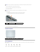
Back to Contents Page Antenna Dell™ Latitude™ 120L Service Manual CAUTION: Before performing the following procedures, follow the safety instructions in the Product Information Guide. CAUTION: To prevent static damage to components inside your computer, discharge static electricity from your body before you touch any of your computer's electronic components. You can do so by touching an unpainted metal surface. 1. Follow the instructions in Before Working Inside Your Computer. 2.
Back to Contents Page
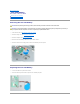
Back to Contents Page Base Plastics Dell™ Latitude™ 120L Service Manual CAUTION: Before performing the following procedures, follow the safety instructions in the Product Information Guide. CAUTION: To prevent static damage to components inside your computer, discharge static electricity from your body before you touch any of your computer's electronic components. You can do so by touching an unpainted metal surface. 1. Follow the instructions in Before Working Inside Your Computer. 2.
Back to Contents Page Before You Begin Dell™ Latitude™ 120L Service Manual Recommended Tools Turning Off Your Computer Before Working Inside Your Computer Computer Orientation Screw Identification This section provides procedures for removing and installing the components in your computer. Unless otherwise noted, each procedure assumes that the following conditions exist: l You have performed the steps in Turning Off Your Computer and Before Working Inside Your Computer.
NOTICE: To disconnect a network cable, first unplug the cable from your computer and then unplug it from the network wall connector. 3. Disconnect any telephone, network, and USB cables from the computer. 4. Disconnect your computer and all attached devices from their electrical outlets. 5. Turn the computer upside-down. NOTICE: To prevent damage to the system board, remove the main battery before you service the computer. 6. 1 Remove the battery: a.
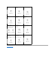
Optical Drive: Fan Module: (1 each) (4 each) Display Assembly to Computer Base: (4 each) Modem to System Board: Display Bezel: Display Panel: (6 each) (8 each) Top of Palm Rest to Computer Base: Base Plastic to Palm Rest From Bottom: Hard Drive Carrier to Hard Drive: (5 each of M2.
Back to Contents Page Coin-Cell Battery Dell™ Latitude™ 120L Service Manual Removing the Coin-Cell Battery Replacing the Coin-Cell Battery Removing the Coin-Cell Battery CAUTION: Before performing the following procedures, follow the safety instructions in the Product Information Guide. CAUTION: To prevent static damage to components inside your computer, discharge static electricity from your body before you touch any of your computer's electronic components.
Back to Contents Page
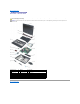
Back to Contents Page System Components Dell™ Latitude™ 120L Service Manual CAUTION: Only a certified service technician should perform repairs on your computer. Damage due to servicing that is not authorized by Dell is not covered by your warranty. NOTICE: Unless otherwise noted, each procedure in this document assumes that a part can be replaced by performing the removal procedure in reverse order.
Back to Contents Page Processor Module Dell™ Latitude™ 120L Service Manual Removing the Processor Module Replacing the Processor Module Removing the Processor Module CAUTION: Before performing the following procedures, follow the safety instructions in the Product Information Guide. CAUTION: To prevent static damage to components inside your computer, discharge static electricity from your body before you touch any of your computer's electronic components.
1. Align the pin-1 corner of the processor module so that it points to the triangle on the system board, and insert the processor module into the ZIF socket. When the processor module is correctly seated, all four corners are aligned at the same height. If one or more corners of the module are higher than the others, the module is not seated correctly. NOTICE: Hold the processor down while turning the cam screw to prevent intermittent contact between the cam screw and processor. 2.
Back to Contents Page Processor Thermal-Cooling Assembly Dell™ Latitude™ 120L Service Manual Removing the Processor Thermal-Cooling Assembly Replacing the Processor Thermal-Cooling Assembly Removing the Processor Thermal-Cooling Assembly CAUTION: Before performing the following procedures, follow the safety instructions in the Product Information Guide.
Replacing the Processor Thermal-Cooling Assembly NOTICE: Before you install the replacement processor thermal-cooling assembly, remove the mylar that covers the thermal grease on the assembly. 1. Lower the processor thermal-cooling assembly into place on top of the processor, aligning the numbered screws, labeled "1" through "4," with the numbers on the fan assembly, and the arrow on the pull-strap pointing toward the outside edge of the system board. 2.
Back to Contents Page Display Assembly Dell™ Latitude™ 120L Service Manual Removing the Display Assembly Removing the Display Bezel Removing the Display Panel Replacing the Display Panel Removing the Display Assembly CAUTION: Before performing the following procedures, follow the safety instructions in the Product Information Guide.
1 antenna cable 1 antenna cable 2 2 display cable display-cable pull-tab NOTICE: Be careful not to damage the display switch when removing the display. 12. Lift the display assembly out of the computer base. Removing the Display Bezel CAUTION: Before performing the following procedures, follow the safety instructions in the Product Information Guide.
1 screw covers/display bumpers (6) 4 top cover 2 M2.5 x 5-mm screws (6) 3 display bezel Removing the Display Panel CAUTION: Before performing the following procedures, follow the safety instructions in the Product Information Guide. CAUTION: To prevent static damage to components inside your computer, discharge static electricity from your body before you touch any of your computer's electronic components. You can do so by touching an unpainted metal surface. 1.
1 display panel 6. 2 top cover 3 M2 x 3-mm screws (8) Press in both sides of the top flex-cable connector, and pull the top flex-cable connector away from the display connector. 1 inverter connector 2 pull-tab on bottom flex-cable connector 3 top flex-cable connector 4 display connector 7. Use the pull-tab to disconnect the bottom flex-cable connector from the inverter connector. Replacing the Display Panel 1. Connect the top flex-cable connector to the display panel connector. 2.
Back to Contents Page Fan Dell™ Latitude™ 120L Service Manual Removing the Cooling Fan Replacing the Cooling Fan Removing the Cooling Fan CAUTION: Before performing the following procedures, follow the safety instructions in the Product Information Guide. CAUTION: To prevent static damage to components inside your computer, discharge static electricity from your body before you touch any of your computer's electronic components. You can do so by touching an unpainted metal surface. 1.
1 fan assembly 17. 2 metal plate 3 M2.5 x 5-mm screws (4) Remove the plate and lift the system board off the fan assembly. Replacing the Cooling Fan 1. Position the system board over the fan assembly, aligning the screw holes in the system board with those in the fan assembly. 2. Place the metal plate over the holes in the system board and replace the four M2.5 x 5-mm screws. 3. Turn the system board over and connect the fan connector to the system board.
Back to Contents Page Flashing the BIOS Dell™ Latitude™ 120L Service Manual Flashing the BIOS From a CD Flashing the BIOS From the Hard Drive If a BIOS-update program CD is provided with the new system board, flash the BIOS from the CD. If you do not have a BIOS-update program CD, flash the BIOS from the hard drive. Flashing the BIOS From a CD 1. Ensure that the AC adapter is plugged in and that the main battery is installed properly.
Back to Contents Page Hard Drive Dell™ Latitude™ 120L Service Manual Removing the Hard Drive Replacing the Hard Drive Removing the Hard Drive CAUTION: If you remove the hard drive from the computer when the drive is hot, do not touch the metal housing of the hard drive. CAUTION: Before you begin any of the procedures in this section, follow the safety instructions in the Product Information Guide. NOTICE: To prevent data loss, turn off your computer before removing the hard drive.
Replacing the Hard Drive 1. Remove the new drive from its packaging. Save the original packaging for storing or shipping the hard drive. NOTICE: Use firm and even pressure to slide the drive into place. If you use excessive force, you may damage the connector. 2. Seat the new hard drive into the bay, and then slide it into the connector by sliding it toward the screw holes until it is fully seated. 3. Replace the cover and tighten the screws. 4.
Back to Contents Page Hinge Cover Dell™ Latitude™ 120L Service Manual Removing the Hinge Cover Replacing the Hinge Cover CAUTION: Before performing the following procedures, follow the safety instructions in the Product Information Guide. CAUTION: To prevent static damage to components inside your computer, discharge static electricity from your body before you touch any of your computer's electronic components. You can do so by touching an unpainted metal surface.
Back to Contents Page Keyboard Dell™ Latitude™ 120L Service Manual Removing the Keyboard Replacing the Keyboard Removing the Keyboard CAUTION: Before working inside your Dell™ computer, follow the safety instructions in your Product Information Guide. CAUTION: To prevent static damage to components inside your computer, discharge static electricity from your body before you touch any of your computer's electronic components. You can do so by touching an unpainted metal surface. 1.
Back to Contents Page
Back to Contents Page Modem Dell™ Latitude™ 120L Service Manual Removing the Modem Replacing the Modem Removing the Modem CAUTION: Before you begin the following procedure, see the safety instructions in the Product Information Guide. NOTICE: To prevent damage to the system board, remove the main battery before working inside the computer. See Before Working Inside Your Computer.
1. Connect the modem cable to the modem. NOTICE: Ensure that the modem cable is routed correctly when you replace the modem. 2. Connect the modem to the system board. Align the connector on the bottom of the modem with the modem connector on the system board, and press down on the connector side of the modem. 3. Replace the two M2 x 3-mm screws.
Back to Contents Page Palm Rest Dell™ Latitude™ 120L Service Manual CAUTION: Before performing the following procedures, follow the safety instructions in the Product Information Guide. CAUTION: To prevent static damage to components inside your computer, discharge static electricity from your body before you touch any of your computer's electronic components. You can do so by touching an unpainted metal surface. 1. Follow the instructions in Before Working Inside Your Computer. 2.
1 suspend switch connector 10. 2 touch-pad ribbon-cable release tabs (2) 3 touch-pad ribbon cable Disconnect the suspend switch connector from the system board. NOTICE: Carefully separate the palm rest from the base plastics to prevent damage to the palm rest. 11. Starting at the back center of the palm rest, use your fingers to separate the palm rest from the base plastics by lifting the inside edge of the palm rest.
Back to Contents Page Pinout Assignments for I/O Connectors Dell™ Latitude™ 120L Service Manual USB Connector Video Connector USB Connector Pin Signal 1 USB5V+ 2 USBP– 3 USBP+ 4 GND Video Connector Pin Signal Pin Signal 1 CRT_R 9 5V+ 2 CRT_G 10 GND 3 CRT_B 11 MONITOR_DETECT– 4 NC 12 DDC_DATA 5 GND 13 CRT_HS 6 GND 14 CRT_VS 7 GND 15 DDC_CLK 8 GND Back to Contents Page
Back to Contents Page Speakers Dell™ Latitude™ 120L Service Manual Removing the Speakers Replacing the Speakers Removing the Speakers CAUTION: Before performing the following procedures, follow the safety instructions in the Product Information Guide. CAUTION: To prevent static damage to components inside your computer, discharge static electricity from your body before you touch any of your computer's electronic components. You can do so by touching an unpainted metal surface.
NOTICE: Ensure that the speaker cables are under or between their routing clips. NOTE: The speakers face out in the base plastics holders. NOTE: The right speaker cable is longer than the left speaker cable. 2. Route the speaker cables under or between their routing clips. 3. Replace the three M2 x 3-mm screws. 4. Connect the speaker connector to the system board.
Back to Contents Page System Board Dell™ Latitude™ 120L Service Manual Removing the System Board Replacing the System Board Removing the System Board CAUTION: Before performing the following procedures, follow the safety instructions in the Product Information Guide. CAUTION: To prevent static damage to components inside your computer, discharge static electricity from your body before you touch any of your computer's electronic components. You can do so by touching an unpainted metal surface.
1 M2.5 x 5-mm screws (5) Replacing the System Board 1. Insert the video connector on the replacement system board through the side of the base plastics. 2. Replace the five M2.5 x 5-mm screws that secure the system board to the base plastics. 3. Reconnect the speakers. See Replacing the Speakers. 4. Replace the modem that you removed from the system board. See Replacing the Modem. 5. Replace the palm rest. See Palm Rest. 6. Replace the display assembly.
Back to Contents Page Dell™ Latitude™ 120L Service Manual NOTE: A NOTE indicates important information that helps you make better use of your computer. NOTICE: A NOTICE indicates either potential damage to hardware or loss of data and tells you how to avoid the problem. CAUTION: A CAUTION indicates a potential for property damage, personal injury, or death. Information in this document is subject to change without notice. © 2006 Dell Inc. All rights reserved.
Back to Contents Page Memory, Optical Drive, and Mini PCI Card Dell™ Latitude™ 120L Service Manual Memory Optical Drive Mini PCI Card Memory Removing a Memory Module CAUTION: Before working inside your Dell™ computer, follow the safety instructions in the Product Information Guide. CAUTION: To prevent static damage to components inside your computer, discharge static electricity from your body before you touch any of your computer's electronic components.
1 memory module 2 securing clips (2 per connector) Replacing the Memory Module 1. Ground yourself and install the new memory module: a. b. 1 Align the notch in the module edge connector with the tab in the connector slot. Slide the module firmly into the slot at a 45-degree angle, and rotate the module down until it clicks into place. If you do not feel the click, remove the module and reinstall it. memory slot notch 2.
1. Close your display and turn the computer upside-down. 2. If a device security screw is present, use a Phillips screwdriver to remove the M2.5 x 8-mm screw. 3. Using a screwdriver or a plastic scribe, push the notch by the device security screw hole toward the outside of the computer. 4. Pull the optical drive straight out of the media bay. 1 optical drive 2 drive removal slot 3 M2.5 x 8-mm device security screw (if present) Replacing the Optical Drive 1.
1 3. captive screws (3) If a Mini PCI card is not already installed, go to step 1. If you are replacing a Mini PCI card, remove the existing card: a. Disconnect the antenna cable from the Mini PCI card. 1 antenna cable b. Release the Mini PCI card by spreading the metal securing tabs until the card pops up slightly. c. Lift the Mini PCI card out of its connector. NOTICE: The connectors are keyed to ensure correct insertion. If you feel resistance, check the connectors and realign the card.
Replacing the Mini PCI Card 1. Install the replacement Mini PCI card. NOTICE: To prevent damage to the Mini PCI card, ensure that the antenna cable is not under the card when you press the card into place. a. 1 Align the Mini PCI card with the connector at a 45-degree angle, and press the Mini PCI card into the connector until it clicks. Mini PCI card b. metal securing tabs (2) Connect the antenna cable to the Mini PCI card.