Dell Latitude 3340 Owner's Manual Regulatory Model: P47G Regulatory Type: P47G001
Notes, cautions, and warnings NOTE: A NOTE indicates important information that helps you make better use of your computer. CAUTION: A CAUTION indicates either potential damage to hardware or loss of data and tells you how to avoid the problem. WARNING: A WARNING indicates a potential for property damage, personal injury, or death. Copyright © 2015 Dell Inc. All rights reserved. This product is protected by U.S. and international copyright and intellectual property laws.
Contents 1 Working on Your Computer............................................................................................. 5 Before Working Inside Your Computer............................................................................................................................... 5 Turning Off Your Computer................................................................................................................................................6 After Working Inside Your Computer...........
Installing the System Board.............................................................................................................................................. 27 3 System Setup............................................................................................................... 29 Boot Sequence.................................................................................................................................................................29 Navigation Keys.................
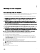
1 Working on Your Computer Before Working Inside Your Computer Use the following safety guidelines to help protect your computer from potential damage and to help to ensure your personal safety. Unless otherwise noted, each procedure included in this document assumes that the following conditions exist: • You have read the safety information that shipped with your computer. • A component can be replaced or--if purchased separately--installed by performing the removal procedure in reverse order.
CAUTION: To guard against electrical shock, always unplug your computer from the electrical outlet before opening the display. CAUTION: Before touching anything inside your computer, ground yourself by touching an unpainted metal surface, such as the metal at the back of the computer. While you work, periodically touch an unpainted metal surface to dissipate static electricity, which could harm internal components. 11. Remove any installed ExpressCards or Smart Cards from the appropriate slots.
CAUTION: To avoid damage to the computer, use only the battery designed for this particular Dell computer. Do not use batteries designed for other Dell computers. 1. Connect any external devices, such as a port replicator, battery slice, or media base, and replace any cards, such as an ExpressCard. 2. Connect any telephone or network cables to your computer. CAUTION: To connect a network cable, first plug the cable into the network device and then plug it into the computer. 3. Replace the battery. 4.
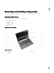
2 Removing and Installing Components This section provides detailed information on how to remove or install the components from your computer. Recommended Tools The procedures in this document may require the following tools: • Small flat-blade screwdriver • #0 Phillips screwdriver • #1 Phillips screwdriver • Small plastic scribe System Overview Figure 1. Front view 1. display 3. keyboard trim 8 2.
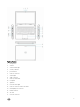
Figure 2. Features 1. microphones 2. camera 3. camera-status light 4. security cable slot 5. power button 6. USB 3.0 connector 7. status lights 8. audio connector 9. memory card reader 10. touchpad 11. speakers 12. network-status light 13. USB 3.0 connector with PowerShare 14. mini DisplayPort connector 15. HDMI connector 16. air vents 17.
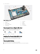
18. power connector Figure 3. Inside view — Back 1. power connector 2. system fan 3. heatsink 4. speaker 5. memory module 6. hard drive 7. audio-connector board 8. WLAN card 9. system board 10. coin-cell battery Removing the Secure Digital (SD) Card 1. Follow the procedures in Before Working Inside Your Computer. 2. Press in on the SD card to release it from the computer. 3. Slide the SD card out of the computer. Installing The Secure Digital (SD) Card 1.
Installing the battery CAUTION: Ensure that both sides of the battery are aligned with the battery slot. If the battery is not aligned correctly, the battery and the battery latches may get damaged. Do not use force while inserting the battery in the battery slot. 1. Align both sides of the battery with the battery slot. 2. Slide the battery into the slot until the battery clicks into place. NOTE: If the battery is not seated firmly, reinstall it. 3.
Installing the SIM Card 1. Insert the SIM card into its slot on the computer and press until it clicks in place. 2. Install the battery. 3. Follow the procedures in After Working Inside Your Computer. Removing the Base Cover 1. Follow the procedures in Before Working On Your Computer. 2. Remove the battery. 3. Perform the following steps to remove the base cover from the computer: a. Remove the screws that secure the base cover to the computer. b.
Installing the Base Cover 1. Align the edges of the base cover on the computer and press it on the computer until it snaps in place. 2. Tighten the screws to secure the base cover to the computer. 3. Install the battery. 4. Follow the procedures in After Working Inside Your Computer. Removing the Memory 1. Follow the procedures in Before Working On Your Computer. 2. Remove the: a. battery b. base cover 3. Perform the following steps to remove the memory module(s) from the computer: a.
3. Remove the keyboard trim from the computer. Installing the Keyboard Trim 1. Align the keyboard trim to its place. 2. Press along the sides of the keyboard trim until it snaps in place. 3. Follow the procedures in After Working Inside Your Computer. NOTE: You may also need to press the center of the keyboard trim to secure the keyboard trim in its place. Removing the Keyboard 1. Follow the procedures in Before Working On Your Computer. 2. Remove the: a. battery b.
3. Remove the screws that secure the keyboard to the computer. 4. Slide down [1] and lift up [2] the keyboard from the computer to access the keyboard cable. 5. Flip the keyboard, disconnect the keyboard cable from its connector, and remove the keyboard from the computer.
Installing the Keyboard 1. Connect the keyboard cable to its connector on the computer. 2. Flip the keyboard and install the keyboard in its place. 3. Tighten the screws to secure the keyboard to the computer. 4. Install the: a. keyboard trim b. battery 5. Follow the procedures in After Working Inside Your Computer. Removing the Coin-Cell Battery 1. Follow the procedures in Before Working on Your Computer 2. Remove: a. battery b. base cover 3.
Installing the Coin-Cell Battery 1. Connect the coin-cell battery cable to the system board. 2. Attach the coin-cell battery to the adhesive on the system board. 3. Install the: a. base cover b. battery 4. Follow the procedures in After Working Inside Your Computer. Removing the Audio-Connector Board 1. Follow the procedures in Before Working On Your Computer. 2. Remove the: a. battery b. base cover 3. Perform the following steps to remove the audio-connector board from the computer: a.
a. Remove the screws that secure the hard drive to the computer. Slide the hard drive to disconnect from its connector on the system board. b. Lift and remove the hard drive from the computer. Installing the Hard Drive 1. Align the hard drive on its bay on the computer. 2. Slide the hard drive into its connector on the system board. 3. Tighten the screws to secure the hard drive to the computer. 4. Install the: a. base cover b. battery 5.
4. Dislodge the speaker tabs from the holders on the computer [1]. Lift and remove the speakers from the computer [2]. Installing the Speakers 1. Replace the speakers in its place and route the cable through the channels. 2. Press down on the speakers until the tabs on the speakers snap onto the holders on the computer. 3. Connect the speaker cable to the system board. 4. Install the: a. base cover b. battery 5. Follow the procedures in After Working Inside Your Computer.
a. battery b. base cover 3. Remove the adhesive tape that secures the antenna cables to the WLAN card. 4. Perform the following steps to remove the WLAN card: a. Disconnect the antenna cables from the WLAN card. b. Remove the screw that secures the WLAN card to the computer. c. Remove the WLAN card from the computer. Installing the WLAN Card 1. Insert the WLAN card into its connector on the computer. 2. Press the WLAN card down and tighten the screw to secure the WLAN card to the computer. 3.
4. Perform the following steps to remove the WWAN card: a. Disconnect the antenna cables from the WWAN card. b. Remove the screw that secures the WWAN card to the computer. c. Remove the WWAN card from the computer. Installing the WWAN Card 1. Insert the WWAN card into its connector on the computer. 2. Press the WWAN card down and tighten the screw to secure the WWAN card to the computer. 3. Connect the antenna cables to their respective connectors marked on the WWAN card. 4.
NOTE: Disconnecting the power cable is optional. For easy removal of the system fan, it is recommended to disconnect the power cable. c. Remove the screws that secure the system fan to the computer. Lift the system fan away from the computer. Installing the System Fan 1. Perform the following steps to install the system fan: a. b. c. d. 2. Place the system fan in its slot on the computer. Connect the system-fan cable and power cable to the system board.
Removing the Heatsink 1. Follow the procedures in Before Working Inside Your Computer. 2. Remove the: a. battery b. base cover c. system fan 3. Un-route the WLAN antenna cables from their channels on the system board. 4. Loosen the captive screws that secure the heatsink to the computer and remove the heatsink from the computer. Installing the Heatsink 1. Place the heatsink on the computer. 2. Tighten the captive screws to secure the heatsink to the system board. 3.
4. Install the: a. system fan b. base cover c. battery 5. Follow the procedures in After Working Inside Your Computer. Removing the Display Assembly 1. Follow the procedures in Before Working Inside Your Computer. 2. Remove the: a. battery b. base cover 3. Perform the following steps: a. Disconnect the antenna cables from WLAN card. Un-route the antenna cables from the WLAN card. b. Remove the screw that secures the bracket over the display cable and remove the bracket. c.
5. Slide the palmrest assembly away to release the display assembly. Installing the Display Assembly 1. Align the palmrest assembly on the display assembly. 2. Tighten the screws to secure the display hinges to the palmrest assembly. 3. Connect the following cables: a. touch panel b. network connector c. display 4. Align the bracket over the display cable and tighten the screw to secure the bracket to the computer. 5.
Removing the System Board 1. Follow the procedures in Before Working on Your Computer. 2. Remove the: a. b. c. d. e. f. g. h. i. j. k. l. m. n. 3. Disconnect the following cables from the system board: a. b. c. d. e. f. g. 4.
5. Lift and remove the system board from the chassis. Installing the System Board 1. Replace the system board on the chassis. 2. Tighten the screws to secure the system board to the chassis. 3. Connect the following cables to their connectors on the system board: a. b. c. d. e. f. g. 4. power display-cable bracket and display network connector touch panel speaker audio connector touchpad Install the: a.
b. c. d. e. f. g. h. i. j. k. l. m. n. 5. 28 system fan WWAN card WLAN card hard drive audio-connector board coin-cell battery keyboard keyboard trim memory modules base cover SIM card battery SD card Follow the procedures in After Working Inside Your Computer.
3 System Setup System Setup enables you to manage your computer hardware and specify BIOS‐level options.
Keys Navigation NOTE: For the standard graphics browser only. Moves to the previous page till you view the main screen. Pressing in the main screen displays a message that prompts you to save any unsaved changes and restarts the system. Displays the System Setup help file. System Setup Options NOTE: Depending on your computer and its installed devices, the items listed in this section may or may not appear. Table 2.
Option Description NOTE: This option is disabled by default. If you enable this option, the UEFI Networking Protocols that are available are installed, allowing the preOS and the OS networking features to use the enabled NICs. You may have to disable the Enabled w/PXE to use this option. SATA Operation Allows you to configure the internal SATA harddrive controller. The options are: • • Disabled AHCI (Default Setting) NOTE: SATA is configured to support AHCI mode.
Option Description • • • Enable Camera Enable Media Card Disable Media Card Default Setting: All devices are enabled. Table 4. Video Option Description LCD Brightness Allows you to set the panel brightness when the ambient sensor is Off. Table 5. Security Option Description Admin Password Allows you to set, change, or delete the administrator (admin) password.
Option Description • Activate NOTE: The Activate and Disable options will permanently activate or disable the feature and no further changes will be allowed. CPU XD Support Allows you to enable the Execute Disable mode of the processor. Default Setting: Enable CPU XD Support OROM Keyboard Access Allows you to set access to enter the Option ROM Configuration screens using hotkeys during boot process.
Table 7. Performance Option Description Multi Core Support This field specifies whether the process will have one or all cores enabled. The performance of some applications will improve with the additional cores. This option is enabled by default. Allows you to enable or disable multi-core support for the processor. The options are: • • • All (Default Setting) 1 2 Intel SpeedStep Allows you to enable or disable the Intel SpeedStep feature.
Option Description Wireless Radio Control Allows you to control the WLAN and WWAN radio. The options are: • • Control WLAN radio Control WWAN radio Default Setting: both the options are disabled. Wake on LAN/WLAN This option allows the computer to power up from the off state when triggered by a special LAN signal. Wake-up from the Standby state is unaffected by this setting and must be enabled in the operating system. This feature only works when the computer is connected to AC power supply.
Option Description • Fn Lock Options Enable Fn Key Emulation This option when enabled allows the hot key combination + toggle the primary behavior of – between their standard and secondary functions. • Fn Lock Hot Key (Default Setting) – Standard (Default Setting) – Secondary Fastboot Allows you to speed up the boot processes. The options are: • • • Extend BIOS POST Time Minimal (Default Setting) Thorough Auto This option creates an extra pre-boot delay.
Table 12. Maintenance Option Description Service Tag Displays the Service Tag of your computer. Asset Tag Allows you to create a system asset tag if an asset tag is not already set. This option is not set by default. Table 13. System Logs Option Description BIOS Events Displays the BIOS event log and allows you to clear the log. • Thermal Events Displays the Thermal event log and allows you to clear the log.
Password Type Description System password Password that you must enter to log on to your system. Setup password Password that you must enter to access and make changes to the BIOS settings of your computer. CAUTION: The password features provide a basic level of security for the data on your computer. CAUTION: Anyone can access the data stored on your computer if it is not locked and left unattended. NOTE: Your computer is shipped with the system and setup password feature disabled.
6. Press to save the changes and exit from the System Setup. The computer reboots.
4 Diagnostics If you experience a problem with your computer, run the ePSA diagnostics before contacting Dell for technical assistance. The purpose of running diagnostics is to test your computer's hardware without requiring additional equipment or risking data loss. If you are unable to fix the problem yourself, service and support personnel can use the diagnostics results to help you solve the problem.
Battery Status Lights If the computer is connected to an electrical outlet, the battery light operates as follows: Alternately blinking amber light and white light An unauthenticated or unsupported non-Dell AC adapter is attached to your laptop. Alternately blinking amber light with steady white light Temporary battery failure with AC adapter present. Constantly blinking amber light Fatal battery failure with AC adapter present. Light off Battery in full charge mode with AC adapter present.
5 Technical Specifications NOTE: Offerings may vary by region. The following specifications are only those required by law to ship with your computer. For more information about the configuration of your computer, go to Help and Support in your Windows operating system and select the option to view information about your computer.
Audio Volume controls Software program menus, media controls, and keyboard function keys Communications Network adapter 10/100/1000 Mbps Ethernet LAN Wireless • • Internal wireless local area network (WLAN), Bluetooth 4.
Display Z-height Front • • Non-Touch – 22.70 mm (0.89 inch) Touch – 24.40 mm (0.96 inch) Back • • Non-Touch – 22.70 mm (0.89 inch) Touch – 25.60 mm (1.01 inch) Weight (with 4-cell battery) Non-Touch – 3.69 lb (1.67 kg) Maximum resolution 1366 x 768 pixels at 262 K colors Maximum Brightness 200 nits Refresh rate 60 Hz Operating Angle 0° (closed) to 187.5° Minimum Viewing Angles: Horizontal 40/45 @ CR ≥10 Vertical 15/20 @ CR ≥10 Pixel pitch 0.2148 mm x 0.
Battery Voltage: 4-cell 7.40 V 6-cell 11.10 V Life span 300 discharge/charge cycles Approximate charge time of battery with computer off • • 4 cell – 6 hours 6 cell – 8 hours Temperature range: Operating 0 °C to 40 °C (32 °F to 104 °F) Non-operating –40 °C to 70 °C (–40 °F to 158 °F) Coin-cell battery 3 V CR2032 lithium ion AC Adapter Type 65W 65W BFR/PVC free 90W (India only) Input voltage 100 VAC to 240 VAC 100 VAC to 240 VAC 100 VAC to 240 VAC Input current (maximum) 1.70 A 1.
Environmental Altitude (maximum): Operating –15.2 m to 3048 m (–50 to 10,000 ft) 0° C to 35°C Non-Operating -15.20 m to 10,668 m (-50 ft to 35,000 ft) Maximum vibration: Operating 0.66 Grms (2 Hz - 600 Hz) Storage 1.30 Grms (2 Hz - 600 Hz) Maximum shock: Operating 110 G Storage 160 G Airborne contaminant level 46 G1 or lower as defined by ISA-S71.
6 Contacting Dell NOTE: If you do not have an active Internet connection, you can find contact information on your purchase invoice, packing slip, bill, or Dell product catalog. Dell provides several online and telephone-based support and service options. Availability varies by country and product, and some services may not be available in your area. To contact Dell for sales, technical support, or customer service issues: 1. Go to dell.com/support. 2. Select your support category. 3.