Dell Latitude 3400 Service Manual Regulatory Model: P111G Regulatory Type: P111G001
Napomene, oprezi i upozorenja NAPOMENA NAPOMENA ukazuje na važne informacije koje vam pomažu da koristite svoj proizvod na bolji način. OPREZ OPREZ naznačuje moguće oštećenje hardvera ili gubitak podataka i objašnjava kako izbjeći neki problem. UPOZORENJE UPOZORENJE naznačuje moguće oštećenje imovine, osobne ozljede ili smrt. © 2019. Dell Inc. ili njegove podružnice. Sva prava pridržana. Dell, EMC i drugi zaštitni znakovi vlasništvo su tvrtke Dell Inc. ili njezinih podružnica.
Contents 1 Radovi na vašem računalu..............................................................................................................5 Sigurnosne upute...................................................................................................................................................................5 Isključivanje računala — Windows 10..................................................................................................................................
5 Troubleshooting........................................................................................................................103 Dijagnostika poboljšanog testiranja računala prije podizanja sustava – ePSA dijagnostika...................................... 103 Pokretanje ePSA dijagnostike.....................................................................................................................................103 Dijagnostike...............................................................
1 Radovi na vašem računalu Sigurnosne upute preduvjeti Sljedećih uputa pridržavajte se radi zaštite računala od moguće g oštećenja i radi osiguranja osobne zaštite. Ako nije navedeno drugačije, svaki postupak u ovom dokumentu podrazumijeva postojanje sljedećih uvjeta: • • Da ste pročitali sigurnosne upute koje ste dobili zajedno s računalom. Komponenta se može zamijeniti ili, ako je zasebno kupljena, instalirati izvođenjem postupka uklanjanja obrnutim redoslijedom.
NAPOMENA Provjerite je li isključeno računalo i svi uređaji koji su na njega priključeni. Ako se računalo i priključeni uređaji nisu automatski isključili nakon odjave operativnog sustava, pritisnite i približno 6 sekundi držite gumb za uključivanje i isključivanje kako biste ih isključili. Prije radova na unutrašnjosti računala O ovom zadatku Kako biste izbjegli oštećivanje računala, slijedite ove korake prije nego što započnete s radom na unutrašnjosti računala. Koraci 1.
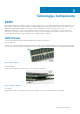
2 Tehnologija i komponente DDR4 DDR4 (double data rate fourth generation) memory is a higher-speed successor to the DDR2 and DDR3 technologies and allows up to 512 GB in capacity, compared to the DDR3's maximum of 128 GB per DIMM. DDR4 synchronous dynamic random-access memory is keyed differently from both SDRAM and DDR to prevent the user from installing the wrong type of memory into the system. DDR4 needs 20 percent less or just 1.2 volts, compared to DDR3 which requires 1.
Figure 3. Curved edge Memory Errors Memory errors on the system display the new ON-FLASH-FLASH or ON-FLASH-ON failure code. If all memory fails, the LCD does not turn on. Troubleshoot for possible memory failure by trying known good memory modules in the memory connectors on the bottom of the system or under the keyboard, as in some portable systems. NOTE: The DDR4 memory is imbedded in board and not a replaceable DIMM as shown and referred.
USB 3.0/USB 3.1 Gen 1 postiže mnogo bolje performanse primjenom tehničkih izmjena navedenih u nastavku: • • • Dodatna fizička sabirnica koji se dodaje paralelno s postojećom USB 2.0 sabirnicom (pogledajte na slici u nastavku). USB 2.0 je prethodno imao četiri žice (napajanje, uzemljenje i par za diferencijalne podataka); USB 3.0/USB 3.1 Gen 1 dodaje još dva para za diferencijalne signale (primanje i slanje) za kombinaciju od ukupno osam priključaka u priključcima i kablovima. USB 3.0/USB 3.
USB vrsta C USB vrste C je novi, tanki fizički priključak. Sam priključak podržava razne nove USB standarde kao što su USB 3.1 i USB napajanje (USB PD). Alternativni način rada USB vrste C predstavlja novi standard priključka koji je vrlo mali. Njegova veličina je oko jedne trećine starog USB utikača vrste A. To je standard za jedan priključak koji može koristiti svaki uređaj.
Omogućavanje Intel Optane memorije Koraci 1. Na programskoj traci kliknite okvir za pretraživanje i upišite „Intel Rapid Storage Technology“. 2. Kliknite Intel Rapid Storage Technology. 3. Na kartici Status kliknite Enable (Omogući) da biste omogućili memoriju Intel Optane. 4. Na zaslonu upozorenja odaberite kompatibilni brzi pogon, a zatim kliknite Yes (Da) za nastavak omogućivanja memorije Intel Optane. 5.
Ekvivalent grafičke kartice Nvidia GeForce MX130 Tablica 4. Specifikacije za Nvidia GeForce MX130 Funkcija Specifikacije Memorija grafičke kartice 2 GB GDDR5 Tip sabirnice PCI Express 3.0 Memorijsko sučelje GDDR5 Brzine sata 1122 – 1242 (Pojačano) MHz Maksimalna dubina boja N/D (Nije dostupno) Maksimalna učestalost vertikalnog osvježavanja N/D (Nije dostupno) Operacijski sustavi – podrška za grafiku/Video API Windows 10/ DX 12/ OGL4.
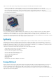
3 Major components of your system 1. Base cover 2.
3. 4. 5. 6. 7. 8. 9. 10. 11. 12. 13. 14. 15. 16. WLAN card Memory modules System board M.2 Solid-state drive or Intel Optane memory—Optional Battery Palmrest assembly Speakers Touchpad assembly Display assembly Hard drive assembly IO board VGA daughterboard System fan Heatsink NOTE: Dell provides a list of components and their part numbers for the original system configuration purchased. These parts are available according to warranty coverages purchased by the customer.
4 Uklanjanje i ugradnja komponenti Recommended tools The procedures in this document require the following tools: • • • Phillips #0 screwdriver Phillips #1 screwdriver Plastic scribe NOTE: The #0 screw driver is for screws 0-1 and the #1 screw driver is for screws 2-4. Secure Digital kartica Uklanjanje Secure Digital kartice preduvjeti 1. Slijedite upute u odlomku Prije rada na unutrašnjosti računala. Koraci 1. Pritisnite Secure Digital karticu kako biste je oslobodili iz računala. 2.
Umetanje Secure Digital kartice Koraci 1. Umetnite Secure Digital karticu u utor tako da klikne na mjesto. 2. Slijedite postupak u odlomku Nakon rada na unutrašnjosti računala. Poklopac kućišta Uklanjanje poklopca kućišta preduvjeti 1. Slijedite postupak u poglavlju Prije rada na unutrašnjosti računala 2. Uklonite SD memorijsku karticu Koraci 1. Otpustite devet pričvrsnih vijaka koji pričvršćuju masku kućišta na sklop oslonca za dlanove i tipkovnice.
2. Odignite masku kućišta i nastavite otvarati desnu stranu maske kućišta.
3. Podignite desnu stranu maske kućišta [1] i uklonite je sa sklopa oslonca za dlanove i tipkovnice [2]. Ugradnja poklopca kućišta Koraci 1. Postavite poklopac kućišta na sklop oslonca za dlanove i tipkovnice [1].
2. Zategnite devet pričvrsnih vijaka koji pričvršćuju masku kućišta na sklop oslonca za dlanove i tipkovnice.
Sljedeæi koraci 1. Ponovno umetnite SD memorijsku karticu 2. Slijedite postupak u odlomku Nakon rada na unutrašnjosti računala Baterija Mjere opreza za litij-ionsku bateriju OPREZ • Budite oprezni kada rukujete litij-ionskim baterijama. • Ispraznite bateriju koliko god možete prije njezina uklanjanja iz sustava. To se može učiniti tako da odspojite strujni adapter iz sustava kako biste omogućili da se baterija isprazni.
2. Uklonite četiri (M2x3) vijka koji pričvršćuju bateriju na sklop oslonca za dlanove i tipkovnice [1]. 3. Podignite bateriju sa sklopa oslonca za dlanove i tipkovnice [2].
Ugradnja baterije Koraci 1. Poravnajte otvore za vijke na bateriji s otvorima za vijke na sklopu oslonca za dlanove i tipkovnice [1]. 2. Ponovno postavite četiri vijka (M2x3) koji pričvršćuju bateriju na sklop oslonca za dlanove i tipkovnice [2].
3. Priključite kabel baterije na matičnu ploču.
Sljedeæi koraci 1. Ponovno postavite poklopac kućišta 2. Ponovno umetnite SD memorijsku karticu 3. Slijedite postupak u odlomku Nakon rada na unutrašnjosti računala Tvrdi pogon Removing the hard drive assembly Prerequisites 1. 2. 3. 4. Follow the procedure in before working inside your computer Remove the SD memory card Remove the base cover Disconnect the battery cable. Steps 1. Disconnect the hard drive cable from the system board [1]. 2.
Installing the hard drive assembly Steps 1. Align the screw holes on the hard drive assembly with the screw holes on the palm rest and keyboard assembly [1]. 2. Replace the four (M2x4.5) screws that secure the hard drive assembly to the palm rest and keyboard assembly [2].
3. Adhere the tape that secures the hard drive cable to the system board [1]. 4. Connect the hard drive cable to the system board [2].
Next steps 1. 2. 3. 4. Replace the battery cable. Replace the base cover Replace the SD memory card Follow the procedure in after working inside your computer IO ploča Removing the IO board Prerequisites 1. 2. 3. 4. 5. Follow the procedure in before working inside your computer. Remove the SD memory card. Remove the base cover. Remove the battery. Remove the hard drive assembly. NOTE: Required for systems with 42 Whr battery Steps 1.
Installing the IO board Steps 1. Using the alignment posts, place the I/O board on the palm rest and keyboard assembly [1]. 2. Replace the two (M2x3) screws that secure the I/O board to the palm rest and keyboard assembly [2].
3. Adhere the I/O board cable to the palm rest and keyboard assembly [1]. 4. Connect the I/O board cable to the system board and close the latch to secure the cable [2].
Next steps 1. Replace the hard drive assembly. NOTE: Required for systems with 42 Whr battery 2. 3. 4. 5. Replace the battery. Replace the base cover. Replace the SD memory card. Follow the procedure in after working inside your computer. Podloga osjetljiva na dodir Removing the touchpad assembly Prerequisites NOTE: For information only, touchpad is included with the palmrest assembly. 1. 2. 3. 4. Follow the procedure in before working inside your computer. Remove the SD memory card.
5. Remove the four (M2x2) screws that secure the touchpad to the palmrest and keyboard assembly [1]. 6. Lift the touchpad off the palmrest and keyboard assembly [2].
Ugradnja sklopa podloge osjetljive na dodir O ovom zadatku NAPOMENA Provjerite je li podloga osjetljiva na dodir poravnata s vodilicama na sklopu oslonca za dlanove i tipkovnice te je li razmak s obje strane podloge jednak. Koraci 1. Postavite podlogu osjetljivu na dodir u utore na sklopu oslonca za dlanove i tipkovnice [1]. 2. Ponovno postavite četiri vijka (M2x2) koji pričvršćuju podlogu osjetljivu na dodir na sklop oslonca za dlanove i tipkovnice [2]. 3.
5. Postavite nosač podloge osjetljivu na dodir u utore na sklopu oslonca za dlanove i tipkovnice [1]. 6. Ponovno postavite tri vijka (M2x2) koji pričvršćuju nosač podloge osjetljive na dodir na sklop oslonca za dlanove i tipkovnice [2] i zalijepite traku koja pričvršćuje nosač na oslonac za dlanove.
Sljedeæi koraci 1. 2. 3. 4. Ponovno postavite bateriju Ponovno postavite poklopac kućišta Ponovno umetnite SD memorijsku karticu Slijedite postupak u odlomku Nakon rada na unutrašnjosti računala Memorijski moduli Removing the memory module Prerequisites 1. 2. 3. 4. Follow the procedure in before working inside your computer Remove the SD memory card Remove the base cover Disconnect the battery cable. Steps 1. Pry the clips securing the memory module until the memory module pops-up [1]. 2.
NOTE: If you do not hear the click, remove the memory module and reinstall it. Next steps 1. 2. 3. 4. Replace the battery cable. Replace the base cover Replace the SD memory card Follow the procedure in after working inside your computer SIM Card Removing the SIM card Prerequisites 1. Follow the procedure in Before working inside your computer Steps 1. Open the latch that covers the SIM card slot to release it from the system [1]. 2. Insert a needle in the slot and push it to eject the SIM card tray [2].
Installing the SIM card Steps 1. Open the latch that covers the SIM card slot to release it from the system [1]. 2. Insert a needle in the slot and push it to eject the SIM card tray [2]. 3. Pull the SIM card try and place the SIM card on the SIM cad tray [3] and [4]. 4. Slide the SIM card tray into the slot until it clicks into place.
5. Follow the procedures in After working inside your computer. WLAN kartica Removing the WLAN card Prerequisites 1. 2. 3. 4. Follow the procedure in before working inside your computer Remove the SD memory card Remove the base cover Disconnect the battery cable. Steps 1. Remove the single (M2x3) screw that secures the WLAN card bracket to the system board [1]. 2. Slide and remove the WLAN card bracket that secures the WLAN cables [2]. 3.
Installing the WLAN card About this task CAUTION: To avoid damage to the WLAN card, do not place any cables under it. Steps 1. Insert the WLAN card into the connector on the system board [1]. 2. Connect the WLAN cables to the connectors on the WLAN card [2]. 3. Place the WLAN card bracket to secure the WLAN cables to the WLAN card [3]. 4. Replace the single (M2x3) screw to secure the WLAN bracket to the WLAN card [4].
Next steps 1. 2. 3. 4. Disconnect the battery cable. Replace the base cover. Replace the SD memory card. Follow the procedure in after working inside your computer. SSD pogon/Intel Optane memorijski modul Removing the M.2 2280 Solid-state drive or Intel Optane memory— Optional Prerequisites NOTE: Disable the Intel Optane memory before removing the Intel Optane memory module from your computer. For more information about disabling the Intel Optane memory, see disabling Intel Optane memory 1. 2. 3. 4.
3. Slide and remove the thermal plate from the solid-state drive/Intel Optane card slot [3]. 4. Remove the single (M2x2) screw that secures the solid-state drive/Intel Optane card to the palmrest and keyboard assembly [1]. 5. Slide and lift the solid-state drive/Intel Optane card off the palmrest and keyboard assembly [2].
Installing the M.2 2280 Solid-state drive or Intel Optane memory Optional Steps 1. Slide and insert the tab solid-state drive/Intel Optane card into the solid-state drive/Intel Optane card slot [1]. 2. Replace the single (M2x2) screw that secures the solid-state drive/Intel Optane card to the palmrest and keyboard assembly [2].
Uklanjanje i ugradnja komponenti
3. Align and replace the thermal plate on the solid-state drive/Intel Optane card slot [1,2]. 4. Replace the single (M2x3) screw that secures the thermal plate to the palmrest and keyboard assembly [3]. Next steps 1. 2. 3. 4. Replace the battery cable. Replace the base cover Replace the SD memory card Follow the procedure in after working inside your computer Removing the M.2 Solid-state drive bracket Prerequisites 1. 2. 3. 4.
Installing the Solid-state drive bracket Steps 1. Align and replace the solid-state drive bracket on the palmrest and keyboard assembly [1]. 2. Replace the single (M2x3) screw that secures the solid-state drive bracket to the palmrest and keyboard assembly [2].
Next steps 1. 2. 3. 4. Replace the battery cable. Replace the base cover Replace the SD memory card Follow the procedure in after working inside your computer Removing the M.2 2230 Solid-state drive Prerequisites 1. 2. 3. 4. Follow the procedure in before working inside your computer Remove the SD memory card Remove the base cover Disconnect the battery cable Steps 1. Remove the single (M2x3) screw that secures the thermal plate to the palmrest and keyboard assembly [1]. 2.
4. Remove the single (M2x2) screw that secures the solid-state drive to the solid-state drive bracket [1]. 5. Slide and remove the solid-state drive off the solid-state drive slot [2].
Installing the M.2 2230 Solid-state drive Steps 1. Insert the solid-state drive into the solid-state drive slot on the system board [1]. 2. Replace the single (M2x3) screw that secures the solid-state drive to the solid-state drive bracket [2].
3. Align and replace the thermal plate on the solid-state drive [1,2]. 4. Replace the single (M2x3) screw that secures the thermal plate to the palmrest and keyboard assembly [3].
Next steps 1. 2. 3. 4. Replace the battery cable. Replace the base cover Replace the SD memory card Follow the procedure in after working inside your computer Zvučnici Removing the speakers Prerequisites 1. 2. 3. 4. Follow the procedure in before working inside your computer Remove the SD memory card Remove the base cover Disconnect the battery cable. Steps 1. Disconnect the speaker cable from the system board [1]. 2.
3. Lift the speakers, along with the cable, off the palm rest and keyboard assembly.
Installing the speakers About this task NOTE: If the rubber grommets are pushed out when removing the speakers, push them back in before replacing the speakers. Steps 1. Using the alignment posts and rubber grommets, place the speakers in the slots on the palm rest and keyboard assembly.
2. Route the speaker cable through the routing guides on the palm rest and keyboard assembly [1]. 3. Connect the speaker cable to the system board [2].
Next steps 1. 2. 3. 4. Replace the battery cable. Replace the base cover Replace the SD memory card Follow the procedure in after working inside your computer Ventilator sustava Removing the system fan Prerequisites 1. 2. 3. 4. Follow the procedure in before working inside your computer. Remove the SD memory card. Remove the base cover. Remove the battery. Steps 1. Disconnect the VGA board cable [1], and the display cable [2, 3] from the system board .
2. Unroute the VGA board cable and the display cable from the routing guides on the fan [1]. 3. Disconnect the fan cable from the system board [2]. 4. Remove the two (M2x3) screws that secure the fan to the palmrest and keyboard board assembly [1].
5. Lift the fan off the palmrest and keyboard board assembly [2]. Installing the system fan Steps 1. Align the screw holes on the fan with the screw holes on to the palm rest and keyboard board assembly [1]. 2. Replace the two (M2x3) screws that secure the fan to the palm rest and keyboard board assembly [2].
3. Connect the fan cable to the system board [1]. 4. Route the VGA board cable and the display cable through the routing guides on the fan [2].
5. Connect the VGA board cable [1], and the display cable [2, 3] to the system board. Next steps 1. 2. 3. 4. Replace the battery. Replace the base cover. Replace the SD memory card. Follow the procedure in after working inside your computer. Sklop hladila procesora Removing the heatsink—UMA Prerequisites 1. 2. 3. 4. Follow the procedure in before working inside your computer. Remove the SD memory card. Remove the base cover. Remove the battery. Steps 1.
Ugradnja sklopa hladila – UMA Koraci 1. Postavite sklop hladila na matičnu ploču i poravnajte otvore za vijke na sklopu hladilu s otvorima za vijke na matičnoj ploči [1]. 2. Redoslijedom (naznačenim na sklopu hladila) pritegnite četiri pričvrsna vijka koji pričvršćuju sklop hladila na matičnu ploču [2].
Sljedeæi koraci 1. 2. 3. 4. Ponovno postavite bateriju Ponovno postavite poklopac kućišta Ponovno umetnite SD memorijsku karticu Slijedite postupak u odlomku Nakon rada na unutrašnjosti računala Uklanjanje sklopa hladila – odvojenog preduvjeti 1. 2. 3. 4. Slijedite postupak u poglavlju Prije rada na unutrašnjosti računala Uklonite SD memorijsku karticu Uklonite poklopac kućišta Uklonite bateriju Koraci 1. Otpustite sedam pričvrsnih vijaka kojima je sklop hladila pričvršćen na matičnu ploču [1].
Ugradnja sklopa hladila – odvojenog Koraci 1. Postavite sklop hladila na matičnu ploču i poravnajte otvore za vijke na sklopu hladilu s otvorima za vijke na matičnoj ploči [1]. 2. Redoslijedom (naznačenim na sklopu hladila) pritegnite sedam pričvrsnih vijaka koji pričvršćuju sklop hladila na matičnu ploču [2].
Sljedeæi koraci 1. 2. 3. 4. Ponovno postavite bateriju Ponovno postavite poklopac kućišta Ponovno umetnite SD memorijsku karticu Slijedite postupak u odlomku Nakon rada na unutrašnjosti računala VGA pomoćna ploča Removing the VGA daughterboard Prerequisites 1. 2. 3. 4. Follow the procedure in before working inside your computer. Remove the SD memory card. Remove the base cover. Remove the battery. Steps 1. Disconnect the VGA daughterboard cable from the system board [1]. 2.
3. Remove the two (M2x3) screws that secure the VGA daughterboard to the palmrest and keyboard assembly [1]. 4. Lift the VGA daughterboard away from the system [2].
Ugradnja VGA pomoćne ploče Koraci 1. Postavite VGA pomoćnu ploču i poravnajte otvore za vijke na VGA pomoćnoj ploči s otvorima za vijke na sklopu oslonca za dlanove i tipkovnice [1]. 2. Ponovno postavite dva vijka (M2x3) koji pričvršćuju VGA pomoćnu ploču na sklop oslonca za dlanove i tipkovnice [2]. 3. Provedite kabel VGA ploče kroz vodilice na ventilatoru [1], a zatim priključite kabel VGA pomoćne ploče na matičnu ploču [2].
Sljedeæi koraci 1. 2. 3. 4. Ponovno postavite bateriju Ponovno postavite poklopac kućišta Ponovno umetnite SD memorijsku karticu Slijedite postupak u odlomku Nakon rada na unutrašnjosti računala Ploča s gumbom za uključivanje/isključivanje Removing the power button board with optional fingerprint reader Prerequisites 1. 2. 3. 4. 5. 6. Follow the procedure in before working inside your computer. Remove the SD memory card. Remove the base cover. Remove the battery. Remove the system fan.
4. Remove the single (M2x3) screw that secures the power button board to the palmrest and keyboard assembly [1]. 5. Lift the power button board, along with the cable off the palmrest and keyboard assembly [2].
Installing the power button board with optional fingerprint reader Steps 1. Place the power-button board into the slot on the palmrest and keyboard assembly [1]. 2. Replace the single (M2x3) screw that secures the power button board to the palmrest and keyboard assembly [2]. 3. Affix the conductive tape to the power button board [1]. 4. Affix the power button cable to the palmrest and keyboard assembly [2]. 5.
Next steps 1. 2. 3. 4. 5. 6. Replace the display assembly. Replace the system fan. Replace the battery. Replace the base cover. Replace the SD memory card. Follow the procedure in after working inside your computer. Matična ploča Removing the system board Prerequisites 1. 2. 3. 4. 5. 6. 7. 8. 9. 10. Follow the procedure in before working inside your computer. Remove the SD memory card. Remove the base cover. Remove the battery. Remove the WLAN. Remove the Memory. Remove the SSD. Remove the system fan.
a) b) c) d) e) Power button board [1]. Fingerprint reader (optional) [2]. IO board [3]. Touchpad [4]. Keyboard [5]. 2. Disconnect the following cables from the system board: a) DC-in [1, 2]. b) Speaker [3].
3. Remove the three (M2x3) screws and two (M2x2) screws that secure the system board to the palmrest and keyboard assembly [1]. 4. Lift the system board off the palm-rest and keyboard assembly [2].
Installing the system board Steps 1. Align the screw hole on the system board with the screw hole on the palmrest and keyboard assembly [1]. 2. Replace the three (M2x3) screws and two (M2x2) screws that secure the system board to the palmrest and keyboard assembly [2].
3. Connect the following cables to the system board: a) DC-in [1, 2]. b) Speaker [3].
4. Connect the following cables to the system board: a) b) c) d) e) 72 Power button board [1]. Fingerprint reader (optional) [2]. IO board [3]. Touchpad [4]. Keyboard [5].
Next steps 1. 2. 3. 4. 5. 6. 7. 8. 9. 10. Replace the display assembly. Replace the heatsink. Replace the system fan. Replace the SSD. Replace the Memory. Replace the WLAN. Replace the battery. Replace the base cover. Replace the SD memory card. Follow the procedure in after working inside your computer. Sklop zaslona Removing the display assembly Prerequisites 1. 2. 3. 4. 5. Follow the procedure in before working inside your computer. Remove the SD memory card. Remove the base cover. Remove the battery.
3. Unroute the display cable from the routing guides on the palmrest and keyboard assembly [1]. 4. Remove the six (M2.5x5) screws that secure the left and right hinges to the system board, and palmrest and keyboard assembly [2].
5. Lift the palmrest and keyboard assembly at an angle [1]. 6. Continue to lift the palmrest and keyboard assembly until it separates from the hinges [2].
7. Slide and remove the palmrest and keyboard assembly off the display assembly.
8. After performing all the preceding steps, you are left with display assembly. Installing the display assembly About this task NOTE: Ensure that the hinges are opened to the maximum before replacing the display assembly on the palmrest and keyboard assembly. Steps 1. Align and place the palmrest and keyboard assembly under the hinges on the display assembly.
2. Press the hinges down on the system board, and palmrest and keyboard assembly [1]. 3. Seat the palmrest and keyboard assembly on the display assembly [2].
4. Replace the six (M2.5x5) screws that secure the left and right hinges to the system board, and palmrest and keyboard assembly [1]. 5. Route the display cable through the routing guides on the palmrest and keyboard assembly [2].
6. Affix the antenna cables to the system board [1]. 7. Connect the display cable to the connector on the system board [2].
Next steps 1. 2. 3. 4. 5. Replace the WLAN. Replace the battery. Replace the base cover. Replace the SD memory card. Follow the procedure in after working inside your computer. Okvir zaslona Uklanjanje okvira zaslona preduvjeti 1. 2. 3. 4. 5. 6. Slijedite postupak u poglavlju Prije rada na unutrašnjosti računala Uklonite SD memorijsku karticu Uklonite poklopac kućišta Uklonite bateriju Uklonite WLAN Uklonite sklop zaslona Koraci 1.
3. Podignite okvir sa sklopa zaslona.
Ugradnja okvira zaslona Koraci 1. Poravnajte okvir zaslona sa stražnjom maskom zaslona.
2. Nježno pritisnite okvir zaslona tako da sjedne na mjesto.
Sljedeæi koraci 1. 2. 3. 4. 5. 6. Ponovno postavite sklop zaslona Ponovno postavite WLAN Ponovno postavite bateriju Ponovno postavite poklopac kućišta Ponovno umetnite SD memorijsku karticu Slijedite postupak u odlomku Nakon rada na unutrašnjosti računala Ploča zaslona Uklanjanje ploče zaslona preduvjeti 1. 2. 3. 4. 5. 6. 7.
3. Odlijepite traku koja pričvršćuje kabel zaslona na stražnju stranu ploče zaslona [1]. 4. Podignite zasun i odspojite kabel zaslona iz priključka kabela ploče zaslona [2]. 5. Podignite ploču zaslona sa stražnje maske zaslona [3].
NAPOMENA Ne vucite i uklonite SR trake s ploče zaslona. Ne trebate odvajati nosače s ploče zaslona. 6. Nakon izvođenja svih prethodnih koraka, preostaje ploča zaslona.
Ugradnja ploče zaslona Koraci 1. Postavite ploču zaslona na ravnu i čistu površinu.
2. Priključite kabel zaslona na priključak na stražnjoj strani ploče zaslona i zatvorite zasun kako biste pričvrstili kabel [1]. 3. Zalijepite traku koja pričvršćuje kabel zaslona na stražnju stranu ploče zaslona [2]. 4. Preokrenite ploču zaslona i postavite je na stražnju masku zaslona [3].
5. Poravnajte otvore za vijke na ploči zaslona s otvorima za vijke na stražnjoj masci zaslona [1]. 6. Ponovno postavite šest (M2x2) i dva (M2x3) vijka koji pričvršćuju ploču zaslona na stražnju masku zaslona [2].
Sljedeæi koraci 1. 2. 3. 4. 5. 6. 7. Ponovno postavite okvir zaslona Ponovno postavite sklop zaslona Ponovno postavite WLAN Ponovno postavite bateriju Ponovno postavite poklopac kućišta Ponovno umetnite SD memorijsku karticu Slijedite postupak u odlomku Nakon rada na unutrašnjosti računala Kabel zaslona Uklanjanje kabela zaslona preduvjeti 1. 2. 3. 4. 5. 6. 7. 8.
Koraci 1. Uklonite kabel kamere i kabel zaslona iz vodilica na stražnjoj masci zaslona [1,2]. 2. Odlijepite traku koja pričvršćuje kabel kamere [3]. 3. Podignite kabel kamere i kabel zaslona sa stražnje maske zaslona.
Ugradnja kabela zaslona Koraci 1. Postavite kabel zaslona i kabel kamere na stražnju masku zaslona.
2. Provucite kabel zaslona i kabel kamere kroz vodilice na sklopu stražnje maske zaslona i antene [1,2]. 3. Zalijepite traku koja pričvršćuje kabel kamere [3].
Sljedeæi koraci 1. 2. 3. 4. 5. 6. 7. 8. Ponovno postavite ploču zaslona Ponovno postavite okvir zaslona Ponovno postavite sklop zaslona Ponovno postavite WLAN Ponovno postavite bateriju Ponovno postavite poklopac kućišta Ponovno umetnite SD memorijsku karticu Slijedite postupak u odlomku Nakon rada na unutrašnjosti računala Ulaz adaptera za napajanje Removing the power adapter port Prerequisites 1. 2. 3. 4. 5.
Ugradnja priključka adaptera za napajanje Koraci 1. Postavite priključak adaptera za napajanje u utor na sklopu oslonca za dlanove i tipkovnice [1]. 2. Ponovno postavite (M2x3) vijak koji pričvršćuje priključak adaptera za napajanje na sklop oslonca za dlanove i tipkovnice [2]. 3. Priključite kabel adaptera za napajanje na matičnu ploču [3, 4].
Sljedeæi koraci 1. 2. 3. 4. 5. Ponovno postavite WLAN Ponovno postavite bateriju Ponovno postavite poklopac kućišta Ponovno umetnite SD memorijsku karticu Slijedite postupak u odlomku Nakon rada na unutrašnjosti računala Kamera Removing the camera Prerequisites 1. 2. 3. 4. 5. 6. 7. 8.
Follow the below procedure to remove the camera in systems with the Touch functionality. 4. Peel the tape that secures the camera off the display back-cover [1]. 5. Lift the camera module from the display back-cover [2].
Installing the camera Steps 1. Connect the camera cable to the camera module [1]. 2. Route the camera cable through the routing channels [2]. 3. Using the alignment post, adhere the camera module on the display back-cover [3].
Following is the procedure to install the camera in systems with the Touch functionality. 4. Align and replace the camera module on the display back-cover [1]. 5. Adhere the tape that secures the camera off the display back-cover [2].
Next steps 1. 2. 3. 4. 5. 6. 7. 8. Replace the display panel. Replace the display bezel. Replace the display assembly. Replace the WLAN. Replace the battery. Replace the base cover. Replace the SD memory card. Follow the procedure in after working inside your computer. Sklop oslonca za dlanove i tipkovnice Removing the palmrest and keyboard assembly Prerequisites 1. 2. 3. 4. 5. 6. 7. 8. 9.
10. 11. 12. 13. 14. 15. 16. 17. Remove the touch pad assembly Remove the VGA daughter board Remove the power button board Remove the speakers Remove the system fan Remove the heatsink Remove the system board Remove the display assembly About this task After performing the preceding steps, you are left with the palmrest and keyboard assembly. NOTE: The power button board is not included with the service replacement palmrest assembly.
5 Troubleshooting Dijagnostika poboljšanog testiranja računala prije podizanja sustava – ePSA dijagnostika O ovom zadatku ePSA dijagnostika (poznata i kao dijagnostika sustava) izvršava cjelovitu provjeru hardvera. ePSA dijagnostika ugrađena je u BIOS i BIOS je interno pokreće.
Dijagnostike Tablica 5. Dijagnostike M-BIST L-BIST Svrha dijagnostičkog alata Procjenjuje zdravlje matične ploče radi daljnjeg rješavanja simptoma grešaka poput „No Power” (Nema napajanja), „No Post” (Sustav ne provodi POST) i „No Video” (Nema slike) te smanjivanjima broja ponovljenih obavijesti. Provjerava napaja li matična ploča LCD zaslon tako da pokreće testiranje LCD sabirnice napajanja što dozvoljava izoliranje uzroka simptoma „No Video“ (Nema slike) na matičnu ploču, LCD ili kabel.
NOTE: The diagnostic pattern consists of a two-digit number being represented by a first group of LED blinks (1–9) in amber, followed by a 1.5 s pause with the LED off, and then a second group of LED blinks (1–9) in white. This is then followed by a three second pause, with the LED off, before repeating over again. Each LED blink takes 0.5 s. The system will not shut down when displaying the Diagnostic Error Codes. Diagnostic Error Codes always supersede any other use of the LED.
• • S4— Sustav koristi najmanje energije u usporedbi sa svim drugim stanjima mirovanja. Sustav je skoro u isključenom stanju, očekuje napajanje u mirovanju. Kontekstni podaci zapisuju se na tvrdi pogon. S5 (OFF) — Sustav je u stanju isključivanja.
6 Dobivanje pomoći Kontaktiranje tvrtke Dell preduvjeti NAPOMENA Ako nemate aktivnu vezu s internetom, podatke za kontakt možete naći na računu kojeg ste dobili prilikom kupnje proizvoda, otpremnici, računu ili katalogu proizvoda tvrtke Dell. O ovom zadatku Tvrtka Dell pruža nekoliko opcija za podršku i uslugu kojima možete pristupiti putem interneta ili telefona. Njihova dostupnost ovisi o državi i proizvodu, stoga neke usluge možda neće biti dostupne u vašoj regiji.