Dell Latitude 3400 Service Manual Regulatory Model: P111G Regulatory Type: P111G001
Opmerkingen, voorzorgsmaatregelen,en waarschuwingen OPMERKING: Een OPMERKING duidt belangrijke informatie aan voor een beter gebruik van het product. WAARSCHUWING: WAARSCHUWINGEN duiden potentiële schade aan hardware of potentieel gegevensverlies aan en vertellen u hoe het probleem kan worden vermeden. GEVAAR: LET OP duidt het risico van schade aan eigendommen, lichamelijk letsel of overlijden aan. © 2019 Dell Inc. of zijn dochtermaatschappijen. Alle rechten voorbehouden.
Contents 1 Aan de computer werken............................................................................................................... 5 Veiligheidsinstructies............................................................................................................................................................. 5 Uw computer uitschakelen: Windows 10............................................................................................................................
5 Troubleshooting........................................................................................................................103 Diagnostische Enhanced Pre-Boot System Assessment - ePSA................................................................................ 103 ePSA-diagnostiek uitvoeren....................................................................................................................................... 103 Diagnostiek.....................................................
1 Aan de computer werken Veiligheidsinstructies Vereisten Volg de onderstaande veiligheidsrichtlijnen om uw persoonlijke veiligheid te garanderen en de computer te beschermen tegen mogelijke schade. Tenzij anders aangegeven, wordt er bij elke procedure in dit document van de volgende veronderstellingen uitgegaan: • • U hebt de veiligheidsinformatie geraadpleegd die bij uw computer is geleverd.
Stappen 1. Klik of tik op het 2. Klik of tik op het . en klik of tik vervolgens opAfsluiten. OPMERKING: Zorg ervoor dat de computer en alle aangesloten apparaten zijn uitgeschakeld. Houd de aan-uitknop 6 seconden ingedrukt, indien uw computer en aangesloten apparaten niet automatisch worden uitgeschakeld wanneer u het besturingssysteem afsluit.
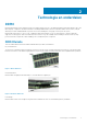
2 Technologie en onderdelen DDR4 DDR4 (double data rate fourth generation) memory is a higher-speed successor to the DDR2 and DDR3 technologies and allows up to 512 GB in capacity, compared to the DDR3's maximum of 128 GB per DIMM. DDR4 synchronous dynamic random-access memory is keyed differently from both SDRAM and DDR to prevent the user from installing the wrong type of memory into the system. DDR4 needs 20 percent less or just 1.2 volts, compared to DDR3 which requires 1.
Figure 3. Curved edge Memory Errors Memory errors on the system display the new ON-FLASH-FLASH or ON-FLASH-ON failure code. If all memory fails, the LCD does not turn on. Troubleshoot for possible memory failure by trying known good memory modules in the memory connectors on the bottom of the system or under the keyboard, as in some portable systems. NOTE: The DDR4 memory is imbedded in board and not a replaceable DIMM as shown and referred.
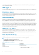
bekend als USB 2.0 en 1.1, werken respectievelijk met een snelheid van 480 Mbps en 12 Mbps. Bovendien zijn beide snelheden achterwaarts compatibel. USB 3.0/USB 3.1 Gen 1 behaalt de veel hogere prestaties door de volgende technische wijzigingen: • • • Een extra fysieke bus die parallel aan de bestaande USB 2.0-bus wordt toegevoegd (zie de afbeelding hieronder). USB 2.0 bevatte vier draden (voeding, aarde en een paar voor differentiële gegevens); USB 3.0/USB 3.
contacten in precies dezelfde locatie als voorheen. Op nieuwe USB 3.0/USB 3.1 Gen 1-kabels zitten vijf nieuwe connectoren voor het onafhankelijk doorgeven van ontvangen en verzonden gegevens. Deze komen alleen in contact wanneer ze zijn aangesloten op een correcte SuperSpeed USB-verbinding. USB Type-C USB Type-C is een nieuwe, kleine, fysieke connector. De connector zelf ondersteunt diverse interessante nieuwe USB-standaarden, zoals USB 3.1 en USB Power Delivery (USB PD).
Feature Specifications • Capacity Intel Rapid Storage Technology driver version 15.9.1.1018 or higher 32 GB or 64 GB Intel Optane geheugen inschakelen Stappen 1. Klik op de taakbalk op het vak Zoeken en typ vervolgens 'Intel Rapid Storage Technology'. 2. Klik op Intel Rapid Storage Technology. 3. Klik op het tabblad Status op Enable (Inschakelen) om het Intel Optane geheugen in te schakelen. 4.
Intel UHD Graphics 620 Operating Systems Graphics/ Video API Support DirectX 12 (Windows 10), OpenGL 4.5 Maximum Vertical Refresh Rate Up to 85 Hz depending on resolution Multiple Display Support On System: eDP (internal), HDMI Via Optional USB Type-C Port: VGA, DisplayPort External Connectors HDMI 1.4b USB Type–C port Nvidia GeForce MX130-equivalent Tabel 4. Nvidia GeForce MX130-specificaties Functie Specificaties Grafisch geheugen 2 GB GDDR5 Bustype PCI Express 3.
3 Major components of your system 1. Base cover 2.
3. 4. 5. 6. 7. 8. 9. 10. 11. 12. 13. 14. 15. 16. WLAN card Memory modules System board M.2 Solid-state drive or Intel Optane memory—Optional Battery Palmrest assembly Speakers Touchpad assembly Display assembly Hard drive assembly IO board VGA daughterboard System fan Heatsink NOTE: Dell provides a list of components and their part numbers for the original system configuration purchased. These parts are available according to warranty coverages purchased by the customer.
4 Onderdelen verwijderen en plaatsen Recommended tools The procedures in this document require the following tools: • • • Phillips #0 screwdriver Phillips #1 screwdriver Plastic scribe NOTE: The #0 screw driver is for screws 0-1 and the #1 screw driver is for screws 2-4. SD-kaart (Secure Digital) De SD-kaart verwijderen Vereisten 1. Volg de procedure in Voordat u in de computer gaat werken. Stappen 1. Druk op de SD-kaart om deze uit de computer te verwijderen. 2. Schuif de SD-kaart uit de computer.
De SD-kaart installeren Stappen 1. Schuif de SD-kaart in de sleuf totdat deze op zijn plaats klikt. 2. Volg de procedures in Nadat u in de computer hebt gewerkt. Onderplaat De onderplaat verwijderen Vereisten 1. Volg de procedure in Voordat u in de computer gaat werken 2. Verwijder de SD-geheugenkaart Stappen 1. Draai de negen borgschroeven los waarmee de onderplaat aan de polssteun- en toetsenbordeenheid is bevestigd.
2. Wrik de onderplaat los en maak de rechterkant van de onderplaat los.
3. Til de rechterkant van de onderplaat [1] omhoog en verwijder deze van de polssteun- en toetsenbordeenheid [2]. De onderplaat plaatsen Stappen 1. Til de onderplaat weg van de polssteun- en toetsenbordeenheid [1].
2. Draai de negen borgschroeven vast waarmee de onderplaat aan de polssteun- en toetsenbordeenheid wordt bevestigd.
Vervolgstappen 1. Plaats de SD-geheugenkaart terug 2. Volg de procedure in Nadat u in de computer hebt gewerkt Batterij Voorzorgsmaatregelen voor de lithium-ionbatterij WAARSCHUWING: • Wees voorzichtig bij het hanteren van lithium-ionbatterijen. • Ontlaad de batterij zo veel mogelijk voordat u deze uit het systeem verwijdert. Dit kan gedaan worden door de netadapter los te koppelen van het systeem, zodat de batterij kan leeglopen.
2. Verwijder de vier schroeven (M2x3) waarmee de batterij aan de polssteun- en toetsenbordeenheid is bevestigd [1]. 3. Til de batterij van de polssteun- en toetsenbordeenheid [2].
De batterij plaatsen Stappen 1. Lijn de schroefgaten op de batterij uit met de schroefgaten op de polssteun- en toetsenbordeenheid [1]. 2. Plaats de vier schroeven (M2x3) terug waarmee de batterij aan de polssteun- en toetsenbordeenheid wordt bevestigd [2].
3. Sluit de batterijkabel aan op het moederbord.
Vervolgstappen 1. Plaats de onderplaat terug 2. Plaats de SD-geheugenkaart terug 3. Volg de procedure in Nadat u in de computer hebt gewerkt Harde schijf Removing the hard drive assembly Prerequisites 1. 2. 3. 4. Follow the procedure in before working inside your computer Remove the SD memory card Remove the base cover Disconnect the battery cable. Steps 1. Disconnect the hard drive cable from the system board [1]. 2. Peel the tape that secures the hard drive cable to the system board [2]. 3.
Installing the hard drive assembly Steps 1. Align the screw holes on the hard drive assembly with the screw holes on the palm rest and keyboard assembly [1]. 2. Replace the four (M2x4.5) screws that secure the hard drive assembly to the palm rest and keyboard assembly [2].
3. Adhere the tape that secures the hard drive cable to the system board [1]. 4. Connect the hard drive cable to the system board [2].
Next steps 1. 2. 3. 4. Replace the battery cable. Replace the base cover Replace the SD memory card Follow the procedure in after working inside your computer I/O-kaart Removing the IO board Prerequisites 1. 2. 3. 4. 5. Follow the procedure in before working inside your computer. Remove the SD memory card. Remove the base cover. Remove the battery. Remove the hard drive assembly. NOTE: Required for systems with 42 Whr battery Steps 1.
Installing the IO board Steps 1. Using the alignment posts, place the I/O board on the palm rest and keyboard assembly [1]. 2. Replace the two (M2x3) screws that secure the I/O board to the palm rest and keyboard assembly [2].
3. Adhere the I/O board cable to the palm rest and keyboard assembly [1]. 4. Connect the I/O board cable to the system board and close the latch to secure the cable [2].
Next steps 1. Replace the hard drive assembly. NOTE: Required for systems with 42 Whr battery 2. 3. 4. 5. Replace the battery. Replace the base cover. Replace the SD memory card. Follow the procedure in after working inside your computer. Toetsenblok Removing the touchpad assembly Prerequisites NOTE: For information only, touchpad is included with the palmrest assembly. 1. 2. 3. 4. Follow the procedure in before working inside your computer. Remove the SD memory card. Remove the base cover.
5. Remove the four (M2x2) screws that secure the touchpad to the palmrest and keyboard assembly [1]. 6. Lift the touchpad off the palmrest and keyboard assembly [2].
De touchpadassemblage plaatsen Over deze taak OPMERKING: Zorg ervoor dat de touchpad is uitgelijnd met de geleiders op de polssteun- en toetsenbordeenheid, en dat de speling aan beide zijden van de touchpad gelijk is. Stappen 1. Plaats de touchpad in de sleuf op de polssteun- en toetsenbordassemblage [1]. 2. Plaats de vier schroeven (M2x2) terug waarmee de touchpad aan de polssteun- en toetsenbordassemblage wordt bevestigd [2]. 3.
5. Plaats de touchpadbeugel in de sleuf op de polssteun- en toetsenbordassemblage [1]. 6. Plaats de drie schroeven (M2x2) terug waarmee de touchpad aan de palmsteun- en toetsenbordeenheid wordt bevestigd [2], en bevestig de tape waarmee de beugel aan de palmsteun wordt bevestigd.
Vervolgstappen 1. 2. 3. 4. Plaats de batterij terug Plaats de onderplaat terug Plaats de SD-geheugenkaart terug Volg de procedure in Nadat u in de computer hebt gewerkt Geheugenmodules Removing the memory module Prerequisites 1. 2. 3. 4. Follow the procedure in before working inside your computer Remove the SD memory card Remove the base cover Disconnect the battery cable. Steps 1. Pry the clips securing the memory module until the memory module pops-up [1]. 2.
NOTE: If you do not hear the click, remove the memory module and reinstall it. Next steps 1. 2. 3. 4. Replace the battery cable. Replace the base cover Replace the SD memory card Follow the procedure in after working inside your computer SIM Card Removing the SIM card Prerequisites 1. Follow the procedure in Before working inside your computer Steps 1. Open the latch that covers the SIM card slot to release it from the system [1]. 2. Insert a needle in the slot and push it to eject the SIM card tray [2].
Installing the SIM card Steps 1. Open the latch that covers the SIM card slot to release it from the system [1]. 2. Insert a needle in the slot and push it to eject the SIM card tray [2]. 3. Pull the SIM card try and place the SIM card on the SIM cad tray [3] and [4]. 4. Slide the SIM card tray into the slot until it clicks into place.
5. Follow the procedures in After working inside your computer. WLAN-kaart Removing the WLAN card Prerequisites 1. 2. 3. 4. Follow the procedure in before working inside your computer Remove the SD memory card Remove the base cover Disconnect the battery cable. Steps 1. Remove the single (M2x3) screw that secures the WLAN card bracket to the system board [1]. 2. Slide and remove the WLAN card bracket that secures the WLAN cables [2]. 3. Disconnect the WLAN cables from the connectors on the WLAN card [3].
Installing the WLAN card About this task CAUTION: To avoid damage to the WLAN card, do not place any cables under it. Steps 1. Insert the WLAN card into the connector on the system board [1]. 2. Connect the WLAN cables to the connectors on the WLAN card [2]. 3. Place the WLAN card bracket to secure the WLAN cables to the WLAN card [3]. 4. Replace the single (M2x3) screw to secure the WLAN bracket to the WLAN card [4].
Next steps 1. 2. 3. 4. Disconnect the battery cable. Replace the base cover. Replace the SD memory card. Follow the procedure in after working inside your computer. Solid State-schijf/Intel Optane-geheugenmodule Removing the M.2 2280 Solid-state drive or Intel Optane memory— Optional Prerequisites NOTE: Disable the Intel Optane memory before removing the Intel Optane memory module from your computer. For more information about disabling the Intel Optane memory, see disabling Intel Optane memory 1. 2. 3.
3. Slide and remove the thermal plate from the solid-state drive/Intel Optane card slot [3]. 4. Remove the single (M2x2) screw that secures the solid-state drive/Intel Optane card to the palmrest and keyboard assembly [1]. 5. Slide and lift the solid-state drive/Intel Optane card off the palmrest and keyboard assembly [2].
Installing the M.2 2280 Solid-state drive or Intel Optane memory Optional Steps 1. Slide and insert the tab solid-state drive/Intel Optane card into the solid-state drive/Intel Optane card slot [1]. 2. Replace the single (M2x2) screw that secures the solid-state drive/Intel Optane card to the palmrest and keyboard assembly [2].
Onderdelen verwijderen en plaatsen
3. Align and replace the thermal plate on the solid-state drive/Intel Optane card slot [1,2]. 4. Replace the single (M2x3) screw that secures the thermal plate to the palmrest and keyboard assembly [3]. Next steps 1. 2. 3. 4. Replace the battery cable. Replace the base cover Replace the SD memory card Follow the procedure in after working inside your computer Removing the M.2 Solid-state drive bracket Prerequisites 1. 2. 3. 4.
Installing the Solid-state drive bracket Steps 1. Align and replace the solid-state drive bracket on the palmrest and keyboard assembly [1]. 2. Replace the single (M2x3) screw that secures the solid-state drive bracket to the palmrest and keyboard assembly [2].
Next steps 1. 2. 3. 4. Replace the battery cable. Replace the base cover Replace the SD memory card Follow the procedure in after working inside your computer Removing the M.2 2230 Solid-state drive Prerequisites 1. 2. 3. 4. Follow the procedure in before working inside your computer Remove the SD memory card Remove the base cover Disconnect the battery cable Steps 1. Remove the single (M2x3) screw that secures the thermal plate to the palmrest and keyboard assembly [1]. 2.
4. Remove the single (M2x2) screw that secures the solid-state drive to the solid-state drive bracket [1]. 5. Slide and remove the solid-state drive off the solid-state drive slot [2].
Installing the M.2 2230 Solid-state drive Steps 1. Insert the solid-state drive into the solid-state drive slot on the system board [1]. 2. Replace the single (M2x3) screw that secures the solid-state drive to the solid-state drive bracket [2].
3. Align and replace the thermal plate on the solid-state drive [1,2]. 4. Replace the single (M2x3) screw that secures the thermal plate to the palmrest and keyboard assembly [3].
Next steps 1. 2. 3. 4. Replace the battery cable. Replace the base cover Replace the SD memory card Follow the procedure in after working inside your computer Luidsprekers Removing the speakers Prerequisites 1. 2. 3. 4. Follow the procedure in before working inside your computer Remove the SD memory card Remove the base cover Disconnect the battery cable. Steps 1. Disconnect the speaker cable from the system board [1]. 2.
3. Lift the speakers, along with the cable, off the palm rest and keyboard assembly.
Installing the speakers About this task NOTE: If the rubber grommets are pushed out when removing the speakers, push them back in before replacing the speakers. Steps 1. Using the alignment posts and rubber grommets, place the speakers in the slots on the palm rest and keyboard assembly.
2. Route the speaker cable through the routing guides on the palm rest and keyboard assembly [1]. 3. Connect the speaker cable to the system board [2].
Next steps 1. 2. 3. 4. Replace the battery cable. Replace the base cover Replace the SD memory card Follow the procedure in after working inside your computer Systeemventilator Removing the system fan Prerequisites 1. 2. 3. 4. Follow the procedure in before working inside your computer. Remove the SD memory card. Remove the base cover. Remove the battery. Steps 1. Disconnect the VGA board cable [1], and the display cable [2, 3] from the system board .
2. Unroute the VGA board cable and the display cable from the routing guides on the fan [1]. 3. Disconnect the fan cable from the system board [2]. 4. Remove the two (M2x3) screws that secure the fan to the palmrest and keyboard board assembly [1].
5. Lift the fan off the palmrest and keyboard board assembly [2]. Installing the system fan Steps 1. Align the screw holes on the fan with the screw holes on to the palm rest and keyboard board assembly [1]. 2. Replace the two (M2x3) screws that secure the fan to the palm rest and keyboard board assembly [2].
3. Connect the fan cable to the system board [1]. 4. Route the VGA board cable and the display cable through the routing guides on the fan [2].
5. Connect the VGA board cable [1], and the display cable [2, 3] to the system board. Next steps 1. 2. 3. 4. Replace the battery. Replace the base cover. Replace the SD memory card. Follow the procedure in after working inside your computer. Warmteafleider Removing the heatsink—UMA Prerequisites 1. 2. 3. 4. Follow the procedure in before working inside your computer. Remove the SD memory card. Remove the base cover. Remove the battery. Steps 1.
De warmteafleider plaatsen - UMA Stappen 1. Plaats de warmteafleider op het moederbord en lijn de schroefgaten op de warmteafleider uit met de schroefgaten op het moederbord [1]. 2. Draai de vier geborgde schroeven waarmee de warmteafleider aan het moederbord is bevestigd in de juiste volgorde (zoals aangegeven op de warmteafleider) vast [2].
Vervolgstappen 1. 2. 3. 4. Plaats de batterij terug Plaats de onderplaat terug Plaats de SD-geheugenkaart terug Volg de procedure in Nadat u in de computer hebt gewerkt De warmteafleider verwijderen - afzonderlijk Vereisten 1. 2. 3. 4. Volg de procedure in Voordat u in de computer gaat werken Verwijder de SD-geheugenkaart Verwijder de onderplaat. Verwijder de batterij. Stappen 1. Maak de zeven borgschroeven los waarmee de warmteafleider aan het moederbord is bevestigd [1].
De warmteafleider plaatsen - afzonderlijk Stappen 1. Plaats de warmteafleider op het moederbord en lijn de schroefgaten op de warmteafleider uit met de schroefgaten op het moederbord [1]. 2. Draai de zeven borgschroeven waarmee de warmteafleider aan het moederbord wordt bevestigd in de juiste volgorde (zoals aangegeven op de warmteafleider) vast [2].
Vervolgstappen 1. 2. 3. 4. Plaats de batterij terug Plaats de onderplaat terug Plaats de SD-geheugenkaart terug Volg de procedure in Nadat u in de computer hebt gewerkt VGA-dochterkaart Removing the VGA daughterboard Prerequisites 1. 2. 3. 4. Follow the procedure in before working inside your computer. Remove the SD memory card. Remove the base cover. Remove the battery. Steps 1. Disconnect the VGA daughterboard cable from the system board [1]. 2.
3. Remove the two (M2x3) screws that secure the VGA daughterboard to the palmrest and keyboard assembly [1]. 4. Lift the VGA daughterboard away from the system [2].
De VGA-dochterkaart plaatsen Stappen 1. Plaats de VGA-dochterkaart en lijn de schroefgaten op de VGA-dochterkaart uit met de schroefgaten op de palmsteun- en toetsenbordeenheid [1]. 2. Plaats de twee schroeven (M2x3) terug waarmee de VGA-dochterkaart aan de palmsteun- en toetsenbordeenheid wordt bevestigd [2]. 3. Leid de kabel van de VGA-kaart door de geleiders op de ventilator [1] en sluit de kabel vervolgens aan op het moederbord [2].
Vervolgstappen 1. 2. 3. 4. Plaats de batterij terug Plaats de onderplaat terug Plaats de SD-geheugenkaart terug Volg de procedure in Nadat u in de computer hebt gewerkt Aan-uitknopkaart Removing the power button board with optional fingerprint reader Prerequisites 1. 2. 3. 4. 5. 6. Follow the procedure in before working inside your computer. Remove the SD memory card. Remove the base cover. Remove the battery. Remove the system fan. Remove the display assembly. Steps 1.
4. Remove the single (M2x3) screw that secures the power button board to the palmrest and keyboard assembly [1]. 5. Lift the power button board, along with the cable off the palmrest and keyboard assembly [2].
Installing the power button board with optional fingerprint reader Steps 1. Place the power-button board into the slot on the palmrest and keyboard assembly [1]. 2. Replace the single (M2x3) screw that secures the power button board to the palmrest and keyboard assembly [2]. 3. Affix the conductive tape to the power button board [1]. 4. Affix the power button cable to the palmrest and keyboard assembly [2]. 5.
Next steps 1. 2. 3. 4. 5. 6. Replace the display assembly. Replace the system fan. Replace the battery. Replace the base cover. Replace the SD memory card. Follow the procedure in after working inside your computer. Moederbord Removing the system board Prerequisites 1. 2. 3. 4. 5. 6. 7. 8. 9. 10. Follow the procedure in before working inside your computer. Remove the SD memory card. Remove the base cover. Remove the battery. Remove the WLAN. Remove the Memory. Remove the SSD. Remove the system fan.
a) b) c) d) e) Power button board [1]. Fingerprint reader (optional) [2]. IO board [3]. Touchpad [4]. Keyboard [5]. 2. Disconnect the following cables from the system board: a) DC-in [1, 2]. b) Speaker [3].
3. Remove the three (M2x3) screws and two (M2x2) screws that secure the system board to the palmrest and keyboard assembly [1]. 4. Lift the system board off the palm-rest and keyboard assembly [2].
Installing the system board Steps 1. Align the screw hole on the system board with the screw hole on the palmrest and keyboard assembly [1]. 2. Replace the three (M2x3) screws and two (M2x2) screws that secure the system board to the palmrest and keyboard assembly [2].
3. Connect the following cables to the system board: a) DC-in [1, 2]. b) Speaker [3].
4. Connect the following cables to the system board: a) b) c) d) e) 72 Power button board [1]. Fingerprint reader (optional) [2]. IO board [3]. Touchpad [4]. Keyboard [5].
Next steps 1. 2. 3. 4. 5. 6. 7. 8. 9. 10. Replace the display assembly. Replace the heatsink. Replace the system fan. Replace the SSD. Replace the Memory. Replace the WLAN. Replace the battery. Replace the base cover. Replace the SD memory card. Follow the procedure in after working inside your computer. Beeldschermassemblage Removing the display assembly Prerequisites 1. 2. 3. 4. 5. Follow the procedure in before working inside your computer. Remove the SD memory card. Remove the base cover.
3. Unroute the display cable from the routing guides on the palmrest and keyboard assembly [1]. 4. Remove the six (M2.5x5) screws that secure the left and right hinges to the system board, and palmrest and keyboard assembly [2].
5. Lift the palmrest and keyboard assembly at an angle [1]. 6. Continue to lift the palmrest and keyboard assembly until it separates from the hinges [2].
7. Slide and remove the palmrest and keyboard assembly off the display assembly.
8. After performing all the preceding steps, you are left with display assembly. Installing the display assembly About this task NOTE: Ensure that the hinges are opened to the maximum before replacing the display assembly on the palmrest and keyboard assembly. Steps 1. Align and place the palmrest and keyboard assembly under the hinges on the display assembly.
2. Press the hinges down on the system board, and palmrest and keyboard assembly [1]. 3. Seat the palmrest and keyboard assembly on the display assembly [2].
4. Replace the six (M2.5x5) screws that secure the left and right hinges to the system board, and palmrest and keyboard assembly [1]. 5. Route the display cable through the routing guides on the palmrest and keyboard assembly [2].
6. Affix the antenna cables to the system board [1]. 7. Connect the display cable to the connector on the system board [2].
Next steps 1. 2. 3. 4. 5. Replace the WLAN. Replace the battery. Replace the base cover. Replace the SD memory card. Follow the procedure in after working inside your computer. Montagekader van het beeldscherm Het montagekader van het beeldscherm verwijderen Vereisten 1. 2. 3. 4. 5. 6. Volg de procedure in Voordat u in de computer gaat werken Verwijder de SD-geheugenkaart Verwijder de onderplaat. Verwijder de batterij. Verwijder de WLAN Verwijder het beeldscherm Stappen 1.
3. Verwijder het montagekader van het beeldscherm van de beeldschermeenheid.
Het montagekader van de beeldschermeenheid plaatsen Stappen 1. Lijn het montagekader van het beeldscherm uit met de achterzijde van het beeldscherm.
2. Druk het montagekader van het beeldscherm voorzichtig op zijn plaats.
Vervolgstappen 1. 2. 3. 4. 5. 6. Plaats het beeldscherm terug. Plaats de WLAN terug Plaats de batterij terug Plaats de onderplaat terug Plaats de SD-geheugenkaart terug Volg de procedure in Nadat u in de computer hebt gewerkt Beeldschermpaneel Het beeldschermpaneel verwijderen Vereisten 1. 2. 3. 4. 5. 6. 7. Volg de procedure in Voordat u in de computer gaat werken Verwijder de SD-geheugenkaart Verwijder de onderplaat. Verwijder de batterij.
3. Trek de tape los waarmee de beeldschermkabel wordt bevestigd aan de achterzijde van het beeldschermpaneel [1]. 4. Til de vergrendeling op en koppel de beeldschermkabel los van de connector op het beeldschermpaneel [2]. 5. Til het beeldschermpaneel van de achterzijde van het beeldscherm [3].
OPMERKING: Trek de Stretch-tapes (SR) van het beeldschermpaneel niet los. Het is niet nodig om de beugels van het beeldschermpaneel te scheiden. 6. Nadat u de voorgaande stappen hebt uitgevoerd, blijft het beeldschermpaneel over.
Het beeldschermpaneel plaatsen Stappen 1. Plaats het beeldschermpaneel op een vlak en schoon oppervlak.
2. Sluit de beeldschermkabel aan op de connector op de achterzijde van het beeldschermpaneel en sluit de vergrendeling om de kabel vast te zetten [1]. 3. Bevestig de tape waarmee de beeldschermkabel wordt bevestigd aan de achterzijde van het beeldschermpaneel [2]. 4. Draai het beeldschermpaneel om en plaats het op de achterzijde van het beeldscherm [3].
5. Lijn de schroefgaten in het beeldschermpaneel uit met de schroefgaten aan de achterzijde van het beeldschermpaneel [1]. 6. Plaats de zes (M2x2) en twee (M2x3) schroeven terug waarmee het beeldschermpaneel aan de achterzijde van het beeldscherm wordt bevestigd [2].
Vervolgstappen 1. 2. 3. 4. 5. 6. 7. Plaats het montagekader van het beeldscherm terug Plaats het beeldscherm terug. Plaats de WLAN terug Plaats de batterij terug Plaats de onderplaat terug Plaats de SD-geheugenkaart terug Volg de procedure in Nadat u in de computer hebt gewerkt Beeldschermkabel De beeldschermkabel verwijderen Vereisten 1. 2. 3. 4. 5. 6. 7. 8. Volg de procedure in Voordat u in de computer gaat werken Verwijder de SD-geheugenkaart Verwijder de onderplaat. Verwijder de batterij.
Stappen 1. Verwijder de camerakabel en beeldschermkabel uit de geleiders op de achterzijde van het beeldscherm [1,2]. 2. Trek de tape los waarmee de camerakabel is vastgemaakt [3]. 3. Til de camerakabel en beeldschermkabel uit de achterzijde van het beeldscherm.
De beeldschermkabel plaatsen Stappen 1. Sluit de beeldschermkabel en camerakabel aan op de achterzijde van het beeldscherm.
2. Leid de beeldschermkabel en camerakabel door de geleiders op de achterzijde van het beeldscherm en de antenne-eenheid [1,2]. 3. Bevestig de tape waarmee de camerakabel wordt vastgemaakt [3].
Vervolgstappen 1. 2. 3. 4. 5. 6. 7. 8. Plaats het beeldschermpaneel terug Plaats het montagekader van het beeldscherm terug Plaats het beeldscherm terug. Plaats de WLAN terug Plaats de batterij terug Plaats de onderplaat terug Plaats de SD-geheugenkaart terug Volg de procedure in Nadat u in de computer hebt gewerkt Netadapterpoort Removing the power adapter port Prerequisites 1. 2. 3. 4. 5.
De voedingsadapterpoort plaatsen Stappen 1. Plaats de voedingsadapterpoort in de sleuf op de polssteun- en toetsenbordeenheid [1]. 2. Plaats de enkele schroef (M2x3) terug waarmee de voedingsadapterpoort aan de polssteun- en toetsenbordeenheid is bevestigd [2]. 3. Sluit de voedingsadapterkabel aan op het moederbord [3, 4].
Vervolgstappen 1. 2. 3. 4. 5. Plaats de WLAN terug Plaats de batterij terug Plaats de onderplaat terug Plaats de SD-geheugenkaart terug Volg de procedure in Nadat u in de computer hebt gewerkt Camera Removing the camera Prerequisites 1. 2. 3. 4. 5. 6. 7. 8. Follow the procedure in before working inside your computer Remove the SD memory card Remove the base cover Remove the battery Remove the WLAN Remove the display assembly Remove the display bezel Remove the display panel Steps 1.
Follow the below procedure to remove the camera in systems with the Touch functionality. 4. Peel the tape that secures the camera off the display back-cover [1]. 5. Lift the camera module from the display back-cover [2].
Installing the camera Steps 1. Connect the camera cable to the camera module [1]. 2. Route the camera cable through the routing channels [2]. 3. Using the alignment post, adhere the camera module on the display back-cover [3].
Following is the procedure to install the camera in systems with the Touch functionality. 4. Align and replace the camera module on the display back-cover [1]. 5. Adhere the tape that secures the camera off the display back-cover [2].
Next steps 1. 2. 3. 4. 5. 6. 7. 8. Replace the display panel. Replace the display bezel. Replace the display assembly. Replace the WLAN. Replace the battery. Replace the base cover. Replace the SD memory card. Follow the procedure in after working inside your computer. Polssteun- en toetsenbordeenheid Removing the palmrest and keyboard assembly Prerequisites 1. 2. 3. 4. 5. 6. 7. 8. 9.
10. 11. 12. 13. 14. 15. 16. 17. Remove the touch pad assembly Remove the VGA daughter board Remove the power button board Remove the speakers Remove the system fan Remove the heatsink Remove the system board Remove the display assembly About this task After performing the preceding steps, you are left with the palmrest and keyboard assembly. NOTE: The power button board is not included with the service replacement palmrest assembly.
5 Troubleshooting Diagnostische Enhanced Pre-Boot System Assessment - ePSA Over deze taak De ePSA-diagnose (ook bekend als systeemdiagnose) voert een volledige controle van uw hardware. ePSA maakt deel uit van het BIOS en wordt door het BIOS intern gestart. De ingebouwde systeemdiagnostiek biedt een aantal opties voor specifieke apparaten of apparaatgroepen waarmee u het volgende kunt doen: De ePSA-diagnostiek kan worden geïnitieerd door Fn+PWR in te drukken terwijl u de computer aanzet.
Diagnostiek Tabel 5. Diagnostiek M-BIST L-BIST Doel van het diagnostische hulpprogramma Evalueert de toestand van het moederbord voor meer informatie over de symptomen 'Geen vermogen', 'Geen POST' en 'Geen video' en vermindert herhaalde interventies. Controleert of het systeembord het lcd-beeldscherm van stroom voorziet door een lcd-stroomrailtest uit te voeren om isolatie van het symptoom 'Geen video' op het systeembord, de lcd of de kabel toe te staan.
NOTE: The diagnostic pattern consists of a two-digit number being represented by a first group of LED blinks (1–9) in amber, followed by a 1.5 s pause with the LED off, and then a second group of LED blinks (1–9) in white. This is then followed by a three second pause, with the LED off, before repeating over again. Each LED blink takes 0.5 s. The system will not shut down when displaying the Diagnostic Error Codes. Diagnostic Error Codes always supersede any other use of the LED.
• • • S0 (AAN): het systeem is ingeschakeld. S4: het systeem verbruikt het minste energie vergeleken met alle andere slaapstanden. Het systeem staat bijna in een UIT-stand, dus u kunt druppelvoeding verwachten. De contextgegevens worden naar de harde schijf weggeschreven. S5 (UIT): het systeem staat in een afsluitstand.
6 Behulpzame informatie vinden Contact opnemen met Dell Vereisten OPMERKING: Als u geen actieve internetverbinding hebt, kunt u contactgegevens ook vinden op uw factuur, pakbon, rekening of productcatalogus van Dell. Over deze taak Dell biedt diverse online en telefonische ondersteunings- en servicemogelijkheden. De beschikbaarheid verschilt per land en product en sommige services zijn mogelijk niet beschikbaar in uw regio.