Dell Latitude 3400 Service Manual Regulatory Model: P111G Regulatory Type: P111G001
Megjegyzés, Vigyázat és Figyelmeztetés MEGJEGYZÉS A MEGJEGYZÉSEK a számítógép biztonságosabb és hatékonyabb használatát elősegítő, fontos tudnivalókat tartalmazzák. FIGYELMEZTETÉS A „FIGYELMEZTETÉS” üzenet hardver-meghibásodás vagy adatvesztés potenciális lehetőségére hívja fel a figyelmet, egyben közli a probléma elkerülésének módját. VIGYÁZAT A VIGYÁZAT jelzés az esetleges tárgyi vagy személyi sérülés, illetve életveszély lehetőségére hívja fel a figyelmet. © 2019 Dell Inc. vagy leányvállalatai.
Contents 1 Munka a számítógépen..................................................................................................................5 Biztonsági utasítások.............................................................................................................................................................5 A számítógép kikapcsolása — Windows 10.......................................................................................................................
5 Troubleshooting........................................................................................................................103 Bővített rendszerindítás előtti rendszerfelmérés (ePSA) diagnosztika...................................................................... 103 Az ePSA-diagnosztika futtatása................................................................................................................................ 103 Diagnosztika.....................................................
1 Munka a számítógépen Biztonsági utasítások Elõfeltételek A számítógép potenciális károsodásának elkerülése és a saját biztonsága érdekében ügyeljen az alábbi biztonsági szabályok betartására. Ha másképp nincs jelezve, a jelen dokumentumban leírt minden művelet a következő feltételek teljesülését feltételezi: • • Elolvasta a számítógéphez mellékelt biztonsággal kapcsolatos tudnivalókat.
Lépések 1. Kattintson a 2. Kattintson a ikonra, vagy érintse meg azt. ikonra, vagy érintse meg azt, majd tegyen ugyanígy a Leállítás ikonnal is. MEGJEGYZÉS Győződjön meg arról, hogy a számítógép és a csatlakoztatott eszközök ki vannak kapcsolva. Ha az operációs rendszer leállásakor a számítógép és a csatlakoztatott eszközök nem kapcsolódnak ki automatikusan, akkor a kikapcsoláshoz tartsa nyomva a bekapcsológombot mintegy 6 másodpercig.
2 Technológia és összetevők DDR4 DDR4 (double data rate fourth generation) memory is a higher-speed successor to the DDR2 and DDR3 technologies and allows up to 512 GB in capacity, compared to the DDR3's maximum of 128 GB per DIMM. DDR4 synchronous dynamic random-access memory is keyed differently from both SDRAM and DDR to prevent the user from installing the wrong type of memory into the system. DDR4 needs 20 percent less or just 1.2 volts, compared to DDR3 which requires 1.
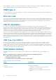
Figure 3. Curved edge Memory Errors Memory errors on the system display the new ON-FLASH-FLASH or ON-FLASH-ON failure code. If all memory fails, the LCD does not turn on. Troubleshoot for possible memory failure by trying known good memory modules in the memory connectors on the bottom of the system or under the keyboard, as in some portable systems. NOTE: The DDR4 memory is imbedded in board and not a replaceable DIMM as shown and referred.
nevén USB 2.0 és 1.1), amelyek továbbra is 480 Mbit/s-os, illetve 12 Mbit/s-os adatátvitelt tesznek lehetővé, megőrizve ezzel a korábbi eszközökkel való kompatibilitást. Az USB 3.0/USB 3.1 Gen 1 a következő műszaki módosítások révén nyújt jóval nagyobb teljesítményt. • • • A meglévő USB 2.0 busszal párhuzamosan egy további fizikai buszt is hozzáadtak (tekintse meg az alábbi képet). Az USB 2.0 korábban négy vezetékkel rendelkezett (táp, földelés és egy pár differenciális adatvezeték). Az USB 3.0/USB 3.
helyen maradt benne. Az USB 3.0/USB 3.1 Gen 1 típusú kábelek öt új kapcsolatot létesítenek az adatok továbbítására és fogadására, de ezeket csak akkor használja az eszköz, ha megfelelő SuperSpeed USB-csatlakozóval érintkezik. USB Type-C Az USB Type-C egy új, kis méretű fizikai csatlakozó. Ez a csatlakozó számos hasznos új USB-szabványt támogat, ilyenek például az USB 3.1 vagy az USB PD (USB-tápellátás). Alternatív mód Az USB Type-C egy új, rendkívül kis méretű csatlakozószabvány.
Feature Specifications Capacity 32 GB or 64 GB Az Intel Optane memória engedélyezése Lépések 1. Kattintson a tálcán található keresőmezőbe, majd írja be: „Intel Rapid Storage Technology”. 2. Kattintson az Intel Rapid Storage Technology lehetőségre. 3. A Status (Állapot) lapon kattintson az Enable (Engedélyezés) lehetőségre az Intel Optane memória letiltásához. 4.
Intel UHD Graphics 620 Via Optional USB Type-C Port: VGA, DisplayPort External Connectors HDMI 1.4b USB Type–C port Nvidia GeForce MX130 egyenértékű 4. táblázat: Nvidia GeForce MX130 – műszaki leírás Funkció Műszaki adatok Grafikus memória 2 GB GDDR5 Busz típusa PCI Express 3.
3 Major components of your system 1. Base cover 2.
3. 4. 5. 6. 7. 8. 9. 10. 11. 12. 13. 14. 15. 16. WLAN card Memory modules System board M.2 Solid-state drive or Intel Optane memory—Optional Battery Palmrest assembly Speakers Touchpad assembly Display assembly Hard drive assembly IO board VGA daughterboard System fan Heatsink NOTE: Dell provides a list of components and their part numbers for the original system configuration purchased. These parts are available according to warranty coverages purchased by the customer.
4 Alkatrészek eltávolítása és beszerelése Recommended tools The procedures in this document require the following tools: • • • Phillips #0 screwdriver Phillips #1 screwdriver Plastic scribe NOTE: The #0 screw driver is for screws 0-1 and the #1 screw driver is for screws 2-4. Secure Digital (SD) kártya A Secure Digital-kártya eltávolítása Elõfeltételek 1. Kövesse a Mielőtt elkezdene dolgozni a számítógép belsejében című fejezet utasításait. Lépések 1.
A Secure Digital-kártya behelyezése Lépések 1. Csúsztassa a Secure Digital-kártyát a foglalatba, amíg az a helyére nem pattan. 2. Kövesse a Miután befejezte a munkát a számítógép belsejében című fejezet utasításait. Alapburkolat Az alapburkolat eltávolítása Elõfeltételek 1. Kövesse a Mielőtt elkezdene dolgozni a számítógép belsejében című fejezet utasításait. 2. Az SD-memóriakártya eltávolítása Lépések 1.
2. Az alapburkolat eltávolítását követően nyissa fel az alapburkolat jobb oldalát.
3. Emelje le az alapburkolatot a jobb oldalról [1], majd emelje le a csuklótámasz- és billentyűzetszerkezetről [2]. Az alapburkolat felszerelése Lépések 1. Helyezze rá az alapburkolatot a csuklótámasz- és billentyűzetszerkezetre [1].
2. Szorítsa meg a kilenc elveszíthetetlen csavart, amelyek az alapburkolatot a csuklótámasz- és billentyűzetszerkezethez rögzítik.
Next steps 1. Helyezze vissza az SD-memóriakártyát 2. Kövesse a Miután befejezte a munkát a számítógép belsejében című fejezet utasításait. Akkumulátor Lítium-ion akkumulátorra vonatkozó figyelmeztetések FIGYELMEZTETÉS • Legyen óvatos a lítium-ion akkumulátorok kezelése során. • A lehető legjobban merítse le az akkumulátort, mielőtt eltávolítaná a rendszerből. Ehhez például húzza ki a tápadaptert a rendszerből, és hagyja, hogy a rendszer folyamatosan merítse az akkumulátort.
2. Távolítsa el az akkumulátort a csuklótámasz- és billentyűzetszerkezethez rögzítő négy csavart (M2x3) [1]. 3. Emelje ki az akkumulátort a csuklótámasz- és billentyűzetszerkezetből [2].
Az akkumulátor beszerelése Lépések 1. Illessze egymáshoz az akkumulátor csavarhelyeit és a csuklótámasz- és billentyűzetszerkezeten lévő csavarhelyeket [1]. 2. Hajtsa be az akkumulátort a csuklótámasz- és billentyűzetszerkezethez rögzítő négy csavart (M2x3) [2].
3. Csatlakoztassa az akkumulátor kábelét az alaplapra.
Next steps 1. Helyezze vissza az alapburkolatot 2. Helyezze vissza az SD-memóriakártyát 3. Kövesse a Miután befejezte a munkát a számítógép belsejében című fejezet utasításait. Merevlemez-meghajtó Removing the hard drive assembly Prerequisites 1. 2. 3. 4. Follow the procedure in before working inside your computer Remove the SD memory card Remove the base cover Disconnect the battery cable. Steps 1. Disconnect the hard drive cable from the system board [1]. 2.
Installing the hard drive assembly Steps 1. Align the screw holes on the hard drive assembly with the screw holes on the palm rest and keyboard assembly [1]. 2. Replace the four (M2x4.5) screws that secure the hard drive assembly to the palm rest and keyboard assembly [2].
3. Adhere the tape that secures the hard drive cable to the system board [1]. 4. Connect the hard drive cable to the system board [2].
Next steps 1. 2. 3. 4. Replace the battery cable. Replace the base cover Replace the SD memory card Follow the procedure in after working inside your computer IO-kártya Removing the IO board Prerequisites 1. 2. 3. 4. 5. Follow the procedure in before working inside your computer. Remove the SD memory card. Remove the base cover. Remove the battery. Remove the hard drive assembly. NOTE: Required for systems with 42 Whr battery Steps 1.
Installing the IO board Steps 1. Using the alignment posts, place the I/O board on the palm rest and keyboard assembly [1]. 2. Replace the two (M2x3) screws that secure the I/O board to the palm rest and keyboard assembly [2].
3. Adhere the I/O board cable to the palm rest and keyboard assembly [1]. 4. Connect the I/O board cable to the system board and close the latch to secure the cable [2].
Next steps 1. Replace the hard drive assembly. NOTE: Required for systems with 42 Whr battery 2. 3. 4. 5. Replace the battery. Replace the base cover. Replace the SD memory card. Follow the procedure in after working inside your computer. Érintőpad Removing the touchpad assembly Prerequisites NOTE: For information only, touchpad is included with the palmrest assembly. 1. 2. 3. 4. Follow the procedure in before working inside your computer. Remove the SD memory card. Remove the base cover.
5. Remove the four (M2x2) screws that secure the touchpad to the palmrest and keyboard assembly [1]. 6. Lift the touchpad off the palmrest and keyboard assembly [2].
Az érintőpanel szerkezetének beszerelése Errõl a feladatról MEGJEGYZÉS Az érintőpanelt igazítsa a csuklótámasz és billentyűzet szerelvényén lévő vezetőkbe úgy, hogy az érintőpanel két oldalán lévő rések egyenlők legyenek. Lépések 1. Helyezze be az érintőpanelt a csuklótámasz- és billentyűzetszerkezet aljzatába [1]. 2. Hajtsa be a négy csavart (M2x2), amely az érintőpanelt a csuklótámasz- és billentyűzetszerkezethez rögzíti [2]. 3.
5. Helyezze be az érintőpanel tartókeretét a csuklótámasz- és billentyűzetszerkezet aljzatába [1]. 6. Hajtsa be a három csavart (M2x2), amely az érintőpanel keretét a csuklótámasz- és billentyűzetszerkezethez rögzíti [2], és ragassza fel a ragasztószalagot, amely a keretet a csuklótámaszra rögzíti.
Next steps 1. 2. 3. 4. Helyezze vissza az elemet Helyezze vissza az alapburkolatot Helyezze vissza az SD-memóriakártyát Kövesse a Miután befejezte a munkát a számítógép belsejében című fejezet utasításait. Memóriamodulok Removing the memory module Prerequisites 1. 2. 3. 4. Follow the procedure in before working inside your computer Remove the SD memory card Remove the base cover Disconnect the battery cable. Steps 1. Pry the clips securing the memory module until the memory module pops-up [1]. 2.
NOTE: If you do not hear the click, remove the memory module and reinstall it. Next steps 1. 2. 3. 4. Replace the battery cable. Replace the base cover Replace the SD memory card Follow the procedure in after working inside your computer SIM Card Removing the SIM card Prerequisites 1. Follow the procedure in Before working inside your computer Steps 1. Open the latch that covers the SIM card slot to release it from the system [1]. 2. Insert a needle in the slot and push it to eject the SIM card tray [2].
Installing the SIM card Steps 1. Open the latch that covers the SIM card slot to release it from the system [1]. 2. Insert a needle in the slot and push it to eject the SIM card tray [2]. 3. Pull the SIM card try and place the SIM card on the SIM cad tray [3] and [4]. 4. Slide the SIM card tray into the slot until it clicks into place.
5. Follow the procedures in After working inside your computer. WLAN-kártya Removing the WLAN card Prerequisites 1. 2. 3. 4. Follow the procedure in before working inside your computer Remove the SD memory card Remove the base cover Disconnect the battery cable. Steps 1. Remove the single (M2x3) screw that secures the WLAN card bracket to the system board [1]. 2. Slide and remove the WLAN card bracket that secures the WLAN cables [2]. 3.
Installing the WLAN card About this task CAUTION: To avoid damage to the WLAN card, do not place any cables under it. Steps 1. Insert the WLAN card into the connector on the system board [1]. 2. Connect the WLAN cables to the connectors on the WLAN card [2]. 3. Place the WLAN card bracket to secure the WLAN cables to the WLAN card [3]. 4. Replace the single (M2x3) screw to secure the WLAN bracket to the WLAN card [4].
Next steps 1. 2. 3. 4. Disconnect the battery cable. Replace the base cover. Replace the SD memory card. Follow the procedure in after working inside your computer. SSD-meghajtó/Intel Optane memóriamodul Removing the M.2 2280 Solid-state drive or Intel Optane memory— Optional Prerequisites NOTE: Disable the Intel Optane memory before removing the Intel Optane memory module from your computer. For more information about disabling the Intel Optane memory, see disabling Intel Optane memory 1. 2. 3. 4.
3. Slide and remove the thermal plate from the solid-state drive/Intel Optane card slot [3]. 4. Remove the single (M2x2) screw that secures the solid-state drive/Intel Optane card to the palmrest and keyboard assembly [1]. 5. Slide and lift the solid-state drive/Intel Optane card off the palmrest and keyboard assembly [2].
Installing the M.2 2280 Solid-state drive or Intel Optane memory Optional Steps 1. Slide and insert the tab solid-state drive/Intel Optane card into the solid-state drive/Intel Optane card slot [1]. 2. Replace the single (M2x2) screw that secures the solid-state drive/Intel Optane card to the palmrest and keyboard assembly [2].
Alkatrészek eltávolítása és beszerelése
3. Align and replace the thermal plate on the solid-state drive/Intel Optane card slot [1,2]. 4. Replace the single (M2x3) screw that secures the thermal plate to the palmrest and keyboard assembly [3]. Next steps 1. 2. 3. 4. Replace the battery cable. Replace the base cover Replace the SD memory card Follow the procedure in after working inside your computer Removing the M.2 Solid-state drive bracket Prerequisites 1. 2. 3. 4.
Installing the Solid-state drive bracket Steps 1. Align and replace the solid-state drive bracket on the palmrest and keyboard assembly [1]. 2. Replace the single (M2x3) screw that secures the solid-state drive bracket to the palmrest and keyboard assembly [2].
Next steps 1. 2. 3. 4. Replace the battery cable. Replace the base cover Replace the SD memory card Follow the procedure in after working inside your computer Removing the M.2 2230 Solid-state drive Prerequisites 1. 2. 3. 4. Follow the procedure in before working inside your computer Remove the SD memory card Remove the base cover Disconnect the battery cable Steps 1. Remove the single (M2x3) screw that secures the thermal plate to the palmrest and keyboard assembly [1]. 2.
4. Remove the single (M2x2) screw that secures the solid-state drive to the solid-state drive bracket [1]. 5. Slide and remove the solid-state drive off the solid-state drive slot [2].
Installing the M.2 2230 Solid-state drive Steps 1. Insert the solid-state drive into the solid-state drive slot on the system board [1]. 2. Replace the single (M2x3) screw that secures the solid-state drive to the solid-state drive bracket [2].
3. Align and replace the thermal plate on the solid-state drive [1,2]. 4. Replace the single (M2x3) screw that secures the thermal plate to the palmrest and keyboard assembly [3].
Next steps 1. 2. 3. 4. Replace the battery cable. Replace the base cover Replace the SD memory card Follow the procedure in after working inside your computer Hangszórók Removing the speakers Prerequisites 1. 2. 3. 4. Follow the procedure in before working inside your computer Remove the SD memory card Remove the base cover Disconnect the battery cable. Steps 1. Disconnect the speaker cable from the system board [1]. 2.
3. Lift the speakers, along with the cable, off the palm rest and keyboard assembly.
Installing the speakers About this task NOTE: If the rubber grommets are pushed out when removing the speakers, push them back in before replacing the speakers. Steps 1. Using the alignment posts and rubber grommets, place the speakers in the slots on the palm rest and keyboard assembly.
2. Route the speaker cable through the routing guides on the palm rest and keyboard assembly [1]. 3. Connect the speaker cable to the system board [2].
Next steps 1. 2. 3. 4. Replace the battery cable. Replace the base cover Replace the SD memory card Follow the procedure in after working inside your computer Rendszerventilátor Removing the system fan Prerequisites 1. 2. 3. 4. Follow the procedure in before working inside your computer. Remove the SD memory card. Remove the base cover. Remove the battery. Steps 1. Disconnect the VGA board cable [1], and the display cable [2, 3] from the system board .
2. Unroute the VGA board cable and the display cable from the routing guides on the fan [1]. 3. Disconnect the fan cable from the system board [2]. 4. Remove the two (M2x3) screws that secure the fan to the palmrest and keyboard board assembly [1].
5. Lift the fan off the palmrest and keyboard board assembly [2]. Installing the system fan Steps 1. Align the screw holes on the fan with the screw holes on to the palm rest and keyboard board assembly [1]. 2. Replace the two (M2x3) screws that secure the fan to the palm rest and keyboard board assembly [2].
3. Connect the fan cable to the system board [1]. 4. Route the VGA board cable and the display cable through the routing guides on the fan [2].
5. Connect the VGA board cable [1], and the display cable [2, 3] to the system board. Next steps 1. 2. 3. 4. Replace the battery. Replace the base cover. Replace the SD memory card. Follow the procedure in after working inside your computer. Hűtőborda Removing the heatsink—UMA Prerequisites 1. 2. 3. 4. Follow the procedure in before working inside your computer. Remove the SD memory card. Remove the base cover. Remove the battery. Steps 1.
A hűtőborda beszerelése – UMA Lépések 1. Helyezze a hűtőbordát az alaplapra, majd illessze a hűtőbordán lévő csavarfuratokat az alaplapon található csavarfuratokhoz [1]. 2. Egymás után (a hűtőbordán jelölt sorrendben) szorítsa meg a hűtőbordát az alaplaphoz rögzítő csavarokat [2].
Next steps 1. 2. 3. 4. Helyezze vissza az elemet Helyezze vissza az alapburkolatot Helyezze vissza az SD-memóriakártyát Kövesse a Miután befejezte a munkát a számítógép belsejében című fejezet utasításait. A hűtőborda eltávolítása – különálló grafikus kártya Elõfeltételek 1. 2. 3. 4. Kövesse a Mielőtt elkezdene dolgozni a számítógép belsejében című fejezet utasításait. Az SD-memóriakártya eltávolítása Távolítsa el az alapburkolatot. Távolítsa el az akkumulátort Lépések 1.
A hűtőborda beszerelése – különálló grafikus kártya Lépések 1. Helyezze a hűtőbordát az alaplapra, majd illessze a hűtőbordán lévő csavarfuratokat az alaplapon található csavarfuratokhoz [1]. 2. Egymás után (a hűtőbordán jelölt sorrendben) szorítsa meg a hűtőbordát az alaplaphoz rögzítő hét elveszíthetetlen csavart [2].
Next steps 1. 2. 3. 4. Helyezze vissza az elemet Helyezze vissza az alapburkolatot Helyezze vissza az SD-memóriakártyát Kövesse a Miután befejezte a munkát a számítógép belsejében című fejezet utasításait. VGA-bővítőkártya Removing the VGA daughterboard Prerequisites 1. 2. 3. 4. Follow the procedure in before working inside your computer. Remove the SD memory card. Remove the base cover. Remove the battery. Steps 1. Disconnect the VGA daughterboard cable from the system board [1]. 2.
3. Remove the two (M2x3) screws that secure the VGA daughterboard to the palmrest and keyboard assembly [1]. 4. Lift the VGA daughterboard away from the system [2].
A VGA-bővítőkártya beszerelése Lépések 1. Helyezze el a VGA-bővítőkártyát, és a VGA-bővítőkártyán lévő csavarlyukakat illessze a csuklótámasz- és billentyűzetszerkezeten lévő csavarlyukakhoz [1]. 2. Hajtsa be a két csavart (M2x3), amely a VGA-bővítőkártyát a csuklótámasz- és billentyűzetszerkezethez rögzíti [2]. 3. Vezesse el a VGA-bővítőkártya kábelét a ventilátor kábelvezetőiben [1], majd csatlakoztassa a VGA-bővítőkártyát az alaplaphoz [2].
Next steps 1. 2. 3. 4. Helyezze vissza az elemet Helyezze vissza az alapburkolatot Helyezze vissza az SD-memóriakártyát Kövesse a Miután befejezte a munkát a számítógép belsejében című fejezet utasításait. Bekapcsológomb-panel Removing the power button board with optional fingerprint reader Prerequisites 1. 2. 3. 4. 5. 6. Follow the procedure in before working inside your computer. Remove the SD memory card. Remove the base cover. Remove the battery. Remove the system fan. Remove the display assembly.
4. Remove the single (M2x3) screw that secures the power button board to the palmrest and keyboard assembly [1]. 5. Lift the power button board, along with the cable off the palmrest and keyboard assembly [2].
Installing the power button board with optional fingerprint reader Steps 1. Place the power-button board into the slot on the palmrest and keyboard assembly [1]. 2. Replace the single (M2x3) screw that secures the power button board to the palmrest and keyboard assembly [2]. 3. Affix the conductive tape to the power button board [1]. 4. Affix the power button cable to the palmrest and keyboard assembly [2]. 5.
Next steps 1. 2. 3. 4. 5. 6. Replace the display assembly. Replace the system fan. Replace the battery. Replace the base cover. Replace the SD memory card. Follow the procedure in after working inside your computer. Alaplap Removing the system board Prerequisites 1. 2. 3. 4. 5. 6. 7. 8. 9. 10. Follow the procedure in before working inside your computer. Remove the SD memory card. Remove the base cover. Remove the battery. Remove the WLAN. Remove the Memory. Remove the SSD. Remove the system fan.
a) b) c) d) e) Power button board [1]. Fingerprint reader (optional) [2]. IO board [3]. Touchpad [4]. Keyboard [5]. 2. Disconnect the following cables from the system board: a) DC-in [1, 2]. b) Speaker [3].
3. Remove the three (M2x3) screws and two (M2x2) screws that secure the system board to the palmrest and keyboard assembly [1]. 4. Lift the system board off the palm-rest and keyboard assembly [2].
Installing the system board Steps 1. Align the screw hole on the system board with the screw hole on the palmrest and keyboard assembly [1]. 2. Replace the three (M2x3) screws and two (M2x2) screws that secure the system board to the palmrest and keyboard assembly [2].
3. Connect the following cables to the system board: a) DC-in [1, 2]. b) Speaker [3].
4. Connect the following cables to the system board: a) b) c) d) e) 72 Power button board [1]. Fingerprint reader (optional) [2]. IO board [3]. Touchpad [4]. Keyboard [5].
Next steps 1. 2. 3. 4. 5. 6. 7. 8. 9. 10. Replace the display assembly. Replace the heatsink. Replace the system fan. Replace the SSD. Replace the Memory. Replace the WLAN. Replace the battery. Replace the base cover. Replace the SD memory card. Follow the procedure in after working inside your computer. Kijelzőszerkezet Removing the display assembly Prerequisites 1. 2. 3. 4. 5. Follow the procedure in before working inside your computer. Remove the SD memory card. Remove the base cover.
3. Unroute the display cable from the routing guides on the palmrest and keyboard assembly [1]. 4. Remove the six (M2.5x5) screws that secure the left and right hinges to the system board, and palmrest and keyboard assembly [2].
5. Lift the palmrest and keyboard assembly at an angle [1]. 6. Continue to lift the palmrest and keyboard assembly until it separates from the hinges [2].
7. Slide and remove the palmrest and keyboard assembly off the display assembly.
8. After performing all the preceding steps, you are left with display assembly. Installing the display assembly About this task NOTE: Ensure that the hinges are opened to the maximum before replacing the display assembly on the palmrest and keyboard assembly. Steps 1. Align and place the palmrest and keyboard assembly under the hinges on the display assembly.
2. Press the hinges down on the system board, and palmrest and keyboard assembly [1]. 3. Seat the palmrest and keyboard assembly on the display assembly [2].
4. Replace the six (M2.5x5) screws that secure the left and right hinges to the system board, and palmrest and keyboard assembly [1]. 5. Route the display cable through the routing guides on the palmrest and keyboard assembly [2].
6. Affix the antenna cables to the system board [1]. 7. Connect the display cable to the connector on the system board [2].
Next steps 1. 2. 3. 4. 5. Replace the WLAN. Replace the battery. Replace the base cover. Replace the SD memory card. Follow the procedure in after working inside your computer. Kijelzőelőlap A kijelzőelőlap eltávolítása Elõfeltételek 1. 2. 3. 4. 5. 6. Kövesse a Mielőtt elkezdene dolgozni a számítógép belsejében című fejezet utasításait. Az SD-memóriakártya eltávolítása Távolítsa el az alapburkolatot. Távolítsa el az akkumulátort A WLAN-kártya eltávolítása Távolítsa el a kijelző szerkezetet. Lépések 1.
3. Emelje ki az előlapot a kijelzőegységből.
A kijelzőelőlap felszerelése Lépések 1. Illessze össze a kijelzőelőlapot a kijelző hátlapjával.
2.
Next steps 1. 2. 3. 4. 5. 6. Helyezze vissza a kijelzőegységet Helyezze vissza a WLAN-kártyát Helyezze vissza az elemet Helyezze vissza az alapburkolatot Helyezze vissza az SD-memóriakártyát Kövesse a Miután befejezte a munkát a számítógép belsejében című fejezet utasításait. Kijelzőpanel A kijelzőpanel eltávolítása Elõfeltételek 1. 2. 3. 4. 5. 6. 7. Kövesse a Mielőtt elkezdene dolgozni a számítógép belsejében című fejezet utasításait. Az SD-memóriakártya eltávolítása Távolítsa el az alapburkolatot.
3. Fejtse le a kijelzőkábelt a kijelzőpanel hátoldalához rögzítő szalagot [1]. 4. Emelje fel a reteszt, és válassza le a kijelző kábelét a kijelzőpanel kábelcsatlakozójáról [2]. 5. Emelje le a kijelzőpanelt a kijelző hátlapjáról [3].
MEGJEGYZÉS Ne húzza ki az SR-szalagokat a kijelzőpanelből, és ne engedje el azokat. Nincs szükség a kereteknek a kijelzőpaneltől való szétválasztására. 6. Az összes előző lépés elvégzése után csak a kijelzőpanel marad.
A kijelzőpanel beszerelése Lépések 1. Helyezze a kijelzőpanelt egyenletes, tiszta felületre.
2. Csatlakoztassa a kijelző kábelét a kijelzőpanel hátoldali csatlakozójához, majd zárja le a reteszt a kábel rögzítéséhez [1]. 3. Ragassza fel a kijelzőkábelt a kijelzőpanel hátoldalához rögzítő szalagot [2]. 4. Fordítsa meg a kijelzőpanelt, és helyezze vissza a kijelzőhátlapra [3].
5. Illessze a kijelzőpanel csavarhelyeit a kijelző hátlapján lévő csavarhelyekhez [1]. 6. Hajtsa be a kijelzőpanelt a kijelző hátlapjához rögzítő hat (M2x2) és két (M2x3) csavart [2].
Next steps 1. 2. 3. 4. 5. 6. 7. Helyezze vissza a kijelzőelőlapot. Helyezze vissza a kijelzőegységet Helyezze vissza a WLAN-kártyát Helyezze vissza az elemet Helyezze vissza az alapburkolatot Helyezze vissza az SD-memóriakártyát Kövesse a Miután befejezte a munkát a számítógép belsejében című fejezet utasításait. Kijelzőkábel A kijelzőkábel eltávolítása Elõfeltételek 1. 2. 3. 4. 5. 6. 7. 8. Kövesse a Mielőtt elkezdene dolgozni a számítógép belsejében című fejezet utasításait.
Lépések 1. Távolítsa el a kamerakábelt és a kijelzőkábelt a kijelző hátlapján lévő kábelvezetőkből [1,2]. 2. Fejtse le az öntapadós szalagot, amely a kamera kábelét rögzíti [3]. 3. Emelje le a kamerakábelt és a kijelzőkábelt a kijelző hátlapjáról.
A kijelzőkábel beszerelése Lépések 1. Helyezze el a kijelző kábelét és a kamera kábelét a kijelző hátlapján.
2. Vezesse el a kijelzőkábelt és a kamerakábelt a kijelzőhátlap- és antennaszerkezet kábelvezetőiben [1,2]. 3. Ragassza fel az öntapadós szalagot, amely a kamera kábelét rögzíti [3].
Next steps 1. 2. 3. 4. 5. 6. 7. 8. Helyezze vissza a kijelzőpanelt. Helyezze vissza a kijelzőelőlapot. Helyezze vissza a kijelzőegységet Helyezze vissza a WLAN-kártyát Helyezze vissza az elemet Helyezze vissza az alapburkolatot Helyezze vissza az SD-memóriakártyát Kövesse a Miután befejezte a munkát a számítógép belsejében című fejezet utasításait. Tápadapterport Removing the power adapter port Prerequisites 1. 2. 3. 4. 5.
A tápadapterport beszerelése Lépések 1. Helyezze be a tápadapterportot a csuklótámasz- és billentyűzetszerkezet aljzatába [1]. 2. Hajtsa be a csavart (M2x3), amely a tápcsatlakozó portot a csuklótámasz és billentyűzetszerkezethez rögzíti [2]. 3. Csatlakoztassa a tápadapter kábelét az alaplaphoz [3, 4].
Next steps 1. 2. 3. 4. 5. Helyezze vissza a WLAN-kártyát Helyezze vissza az elemet Helyezze vissza az alapburkolatot Helyezze vissza az SD-memóriakártyát Kövesse a Miután befejezte a munkát a számítógép belsejében című fejezet utasításait. Kamera Removing the camera Prerequisites 1. 2. 3. 4. 5. 6. 7. 8.
Follow the below procedure to remove the camera in systems with the Touch functionality. 4. Peel the tape that secures the camera off the display back-cover [1]. 5. Lift the camera module from the display back-cover [2].
Installing the camera Steps 1. Connect the camera cable to the camera module [1]. 2. Route the camera cable through the routing channels [2]. 3. Using the alignment post, adhere the camera module on the display back-cover [3].
Following is the procedure to install the camera in systems with the Touch functionality. 4. Align and replace the camera module on the display back-cover [1]. 5. Adhere the tape that secures the camera off the display back-cover [2].
Next steps 1. 2. 3. 4. 5. 6. 7. 8. Replace the display panel. Replace the display bezel. Replace the display assembly. Replace the WLAN. Replace the battery. Replace the base cover. Replace the SD memory card. Follow the procedure in after working inside your computer. Csuklótámasz- és billentyűzetszerkezet Removing the palmrest and keyboard assembly Prerequisites 1. 2. 3. 4. 5. 6. 7. 8. 9.
10. 11. 12. 13. 14. 15. 16. 17. Remove the touch pad assembly Remove the VGA daughter board Remove the power button board Remove the speakers Remove the system fan Remove the heatsink Remove the system board Remove the display assembly About this task After performing the preceding steps, you are left with the palmrest and keyboard assembly. NOTE: The power button board is not included with the service replacement palmrest assembly.
5 Troubleshooting Bővített rendszerindítás előtti rendszerfelmérés (ePSA) diagnosztika Errõl a feladatról Az ePSA diagnosztikai funkció (amely rendszerdiagnosztika néven is ismert) teljes körű ellenőrzést végez a hardveres eszközökön. Az ePSA a BIOS-ba ágyazva található, és a BIOS-ból indítható el.
Diagnosztika 5. táblázat: Diagnosztika M-BIST L-BIST A diagnosztikai eszköz célja Kiértékeli az alaplap állapotát a tápellátási hibák, POST-hibák és videojellel kapcsolatos hibák megoldása és az ismételt alkatrészkiszállítások elkerülése érdekében. Az LCD áramvezető sínjének tesztjével ellenőrzi, hogy az LCD kap-e áramot az alaplaptól, így segít meghatározni, hogy a hiányzó videojellel kapcsolatos probléma az alaplappal, az LCD-vel vagy a kábellel van-e kapcsolatban.
The system will not shut down when displaying the Diagnostic Error Codes. Diagnostic Error Codes always supersede any other use of the LED. For instance, on Notebooks, battery codes for Low Battery or Battery Failure situations will not be displayed when Diagnostic Error Codes are being displayed. Table 6. Diagnostic LED Blinking Pattern Possible Problem Suggested Resolution 1 CPU failure Replace the system board.
6 Hogyan kérhet segítséget A Dell elérhetőségei Elõfeltételek MEGJEGYZÉS Amennyiben nem rendelkezik aktív internetkapcsolattal, elérhetőségeinket megtalálhatja a vásárlást igazoló nyugtán, a csomagoláson, a számlán vagy a Dell termékkatalógusban. Errõl a feladatról A Dell számos támogatási lehetőséget biztosít, online és telefonon keresztül egyaránt.