Dell Latitude 3400 Service Manual Regulatory Model: P111G Regulatory Type: P111G001
Merknader, forholdsregler og advarsler MERK En merknad inneholder viktig informasjon som hjelper deg med å bruke ditt produkt mer effektivt. FORSIKTIG Angir enten potensiell fare for maskinvaren eller tap av data, og forteller hvordan du kan unngå problemet. ADVARSEL ADVARSEL angir potensiell fare for skade på eiendom, personskade eller død. © 2019 Dell Inc. eller deres datterselskaper. Med enerett. Dell og EMC og andre varemerker er varemerker for Dell Inc. eller dets datterselskaper.
Contents 1 Arbeide på datamaskinen...............................................................................................................5 Sikkerhetsanvisninger........................................................................................................................................................... 5 Slå av datamaskinen — Windows 10..................................................................................................................................
5 Troubleshooting........................................................................................................................103 Utvidet systemanalyse før oppstart) – ePSA-diagnostikk........................................................................................... 103 Kjøre ePSA-diagnostikk............................................................................................................................................... 103 Diagnostikk........................................
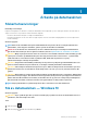
1 Arbeide på datamaskinen Sikkerhetsanvisninger Nødvendige forutsetninger Følg disse retningslinjene for sikkerhet for å beskytte datamaskinen mot mulig skade og verne om din egen sikkerhet. Hvis ikke annet er angitt, forutsetter hver av prosedyrene i dette dokumentet følgende: • • Du har lest sikkerhetsanvisningene som fulgte med datamaskinen. En komponent kan byttes ut eller, hvis enheten er kjøpt separat, settes inn ved å utføre fremgangsmåten for å ta ut komponenten i motsatt rekkefølge.
MERK Forsikre deg om at datamaskinen og alt tilkoblet utstyr er slått av. Hvis datamaskinen og tilkoblet utstyr ikke ble slått av automatisk da du slo av operativsystemet, må du trykke og holde inne strømknappen i ca. 6 sekunder for å slå dem av. Før du foretar arbeid inne i datamaskinen Om denne oppgaven For å unngå å skade datamaskinen må du utføre trinnene nedenfor før du begynner å arbeide inne i datamaskinen. Trinn 1. Sørg for å overholde følgende sikkerhetsinstruksjoner. 2.
2 Teknologi og komponenter DDR4 DDR4 (double data rate fourth generation) memory is a higher-speed successor to the DDR2 and DDR3 technologies and allows up to 512 GB in capacity, compared to the DDR3's maximum of 128 GB per DIMM. DDR4 synchronous dynamic random-access memory is keyed differently from both SDRAM and DDR to prevent the user from installing the wrong type of memory into the system. DDR4 needs 20 percent less or just 1.2 volts, compared to DDR3 which requires 1.
Figure 3. Curved edge Memory Errors Memory errors on the system display the new ON-FLASH-FLASH or ON-FLASH-ON failure code. If all memory fails, the LCD does not turn on. Troubleshoot for possible memory failure by trying known good memory modules in the memory connectors on the bottom of the system or under the keyboard, as in some portable systems. NOTE: The DDR4 memory is imbedded in board and not a replaceable DIMM as shown and referred. USB-funksjoner Universal Serial Bus, USB, ble lansert i 1996.
USB-modusene Hi-Speed og Full-Speed, ofte kalt henholdsvis USB 2.0 og 1.1, kjører de langsommere modusene fortsatt på henholdsvis 480 Mbps og 12 Mbps, og er beholdt for å opprettholde kompatibilitet bakover. USB 3.0/USB 3.1 Gen 1 oppnår mye høyere ytelse med de tekniske endringene nedenfor: • • • En ekstra fysisk buss som er lagt inn parallelt med den eksisterende USB 2.0-bussen (se bildet nedenfor). USB 2.0 hadde tidligere fire ledninger (strøm, jord og et par for differensielle data). USB 3.0/USB 3.
USB type-C USB Type-C er en ny, liten fysisk kontakt. Kontakten selv kan støtte forskjellige spennende nye USB-standarder, f.eks. USB 3.1 og USBPD (USB power delivery). Alternative modus USB Type-C er en ny kontakt-standard som er svært liten. Den er omtrent en tredjedel av størrelsen på en gammel USB Type-A-plugg. Dette er en enkeltkontakt-standard som hver enhet skal kunne bruke.
Enabling Intel Optane memory (Aktivere Intel Optaneminnet) Trinn 1. Klikk på søkeboksen på oppgavelinjen, og skriv inn "Intel Rapid-lagringsteknologi". 2. Intel Rapid-lagringsteknologi 3. Klikk på Aktiver på Status-fanen for å aktivere Intel Optane-minnet. 4. Velg en kompatibel rask stasjon på varselskjermen, og klikk deretter på Ja for å fortsette aktivering av Intel Optane-minnet. 5. Klikk på Intel Optane-minnet > Start på nytt for å aktivere Intel Optane-minnet.
Tilsvarende Nvidia GeForce MX130 Tabell 4. Nvidia GeForce MX130 specifications (Spesifikasjoner for Nvidia GeForce MX130) Funksjon Spesifikasjoner Grafikkminne 2 GB GDDR5 Busstype PCI Express 3.0 Minnegrensesnitt GDDR5 Klokkehastigheter 11221242 MHz (oppstart) Maksimal fargedybde N/A Maksimal vertikal oppdateringsfrekvens N/A Grafikk i operativsystemet/API-støtte for video Windows 10/ DX 12/ OGL4.5 Støttede oppløsninger og maks.
3 Major components of your system 1. Base cover 2.
3. 4. 5. 6. 7. 8. 9. 10. 11. 12. 13. 14. 15. 16. WLAN card Memory modules System board M.2 Solid-state drive or Intel Optane memory—Optional Battery Palmrest assembly Speakers Touchpad assembly Display assembly Hard drive assembly IO board VGA daughterboard System fan Heatsink NOTE: Dell provides a list of components and their part numbers for the original system configuration purchased. These parts are available according to warranty coverages purchased by the customer.
4 Ta ut og installere komponenter Recommended tools The procedures in this document require the following tools: • • • Phillips #0 screwdriver Phillips #1 screwdriver Plastic scribe NOTE: The #0 screw driver is for screws 0-1 and the #1 screw driver is for screws 2-4. Secure Digital-kort Removing the Secure Digital card (Ta ut Secure Digital-kortet) Nødvendige forutsetninger 1. Følg prosedyren i Før du arbeider inne i datamaskinen. Trinn 1. Skyv Secure Digital-kortet for å løsne det fra datamaskinen. 2.
Installing the Secure Digital card (Sette inn Secure Digital-kortet) Trinn 1. Skyv Secure Digital inn i sporet til det klikker på plass. 2. Følg prosedyrene i Etter at du har arbeidet inne i datamaskinen. Bunndeksel Ta av bunndekselet Nødvendige forutsetninger 1. Følg prosedyren i Før du arbeider inne i datamaskinen. 2. Ta ut SD-minnekortet Trinn 1. Løsne de ni festeskruene som fester bunndekselet til håndleddstøtten og tastaturenheten.
2. Lirk bunndekselet, og fortsett for å åpne høyre side av bunndekselet.
3. Løft høyre side av bunndekselet [1], og ta det fra håndleddstøtten og tastaturenheten [2]. Sette på bunndekselet Trinn 1. Sett inn bunndekselet på håndleddstøtten og tastaturenheten [1].
2. Stram de ni festeskruene som fester bunndekselet til håndleddstøtten og tastaturenheten.
Neste trinn 1. Sett inn SD-minnekortet 2. Følg fremgangsmåten i etter at du har arbeidet inne i datamaskinen. Batteri Forholdsregler for litium-ion-batteri FORSIKTIG • Vær forsiktig når du håndterer litium-ion-batterier. • Lad ut batteriet så mye som mulig før du tar det ut av systemet. Dette kan gjøres ved å koble strømadapteren fra systemet for at batteriet skal lades ut. • Ikke knus, slipp, ødelegg eller gjennombore batteriet ved bruk av fremmedlegemer.
2. Fjern (M2x3)-skruene som fester batteriet til håndleddstøtten og tastaturenheten [1]. 3. Løft batteriet fra håndleddstøtten og tastaturenheten [2].
Sette inn batteriet Trinn 1. Juster skruehullene på batteriet etter skruehullene på håndleddsstøtten og tastaturenheten [1]. 2. Fest (M2x3)-skruene som fester batteriet til håndleddstøtten og tastaturenheten [2].
3. Koble batterikabelen til hovedkortet.
Neste trinn 1. Sett på bunndekselet. 2. Sett inn SD-minnekortet 3. Følg fremgangsmåten i etter at du har arbeidet inne i datamaskinen. Harddisk Removing the hard drive assembly Prerequisites 1. 2. 3. 4. Follow the procedure in before working inside your computer Remove the SD memory card Remove the base cover Disconnect the battery cable. Steps 1. Disconnect the hard drive cable from the system board [1]. 2. Peel the tape that secures the hard drive cable to the system board [2]. 3.
Installing the hard drive assembly Steps 1. Align the screw holes on the hard drive assembly with the screw holes on the palm rest and keyboard assembly [1]. 2. Replace the four (M2x4.5) screws that secure the hard drive assembly to the palm rest and keyboard assembly [2].
3. Adhere the tape that secures the hard drive cable to the system board [1]. 4. Connect the hard drive cable to the system board [2].
Next steps 1. 2. 3. 4. Replace the battery cable. Replace the base cover Replace the SD memory card Follow the procedure in after working inside your computer IO-kort Removing the IO board Prerequisites 1. 2. 3. 4. 5. Follow the procedure in before working inside your computer. Remove the SD memory card. Remove the base cover. Remove the battery. Remove the hard drive assembly. NOTE: Required for systems with 42 Whr battery Steps 1.
Installing the IO board Steps 1. Using the alignment posts, place the I/O board on the palm rest and keyboard assembly [1]. 2. Replace the two (M2x3) screws that secure the I/O board to the palm rest and keyboard assembly [2].
3. Adhere the I/O board cable to the palm rest and keyboard assembly [1]. 4. Connect the I/O board cable to the system board and close the latch to secure the cable [2].
Next steps 1. Replace the hard drive assembly. NOTE: Required for systems with 42 Whr battery 2. 3. 4. 5. Replace the battery. Replace the base cover. Replace the SD memory card. Follow the procedure in after working inside your computer. Pekeflate Removing the touchpad assembly Prerequisites NOTE: For information only, touchpad is included with the palmrest assembly. 1. 2. 3. 4. Follow the procedure in before working inside your computer. Remove the SD memory card. Remove the base cover.
5. Remove the four (M2x2) screws that secure the touchpad to the palmrest and keyboard assembly [1]. 6. Lift the touchpad off the palmrest and keyboard assembly [2].
Sette inn styreplateenheten Om denne oppgaven MERK Kontroller at styreplaten er på linje med føringene som finnes på håndstøtten og tastaturet og at gapet på hver side av styreplaten er likt. Trinn 1. Sett styreplaten inn i sporet på håndleddstøtten og tastaturenheten [1]. 2. Fest (M2x2)-skruene som fester styreplaten til håndleddstøtten og tastaturenheten [2]. 3. Fest tapen som fester styreplaten til håndleddstøtten og tastaturenheten [1]. 4.
5. Sett styreplatebraketten inn i sporet på håndleddstøtten og tastaturenheten [1]. 6. Fest (M2x2)-skruene som fester styreplatebraketten til håndleddstøtten og tastaturet [2], og fest tapen som fester braketten til håndleddstøtten.
Neste trinn 1. 2. 3. 4. Sett inn batteriet Sett på bunndekselet. Sett inn SD-minnekortet Følg fremgangsmåten i etter at du har arbeidet inne i datamaskinen. Minnemoduler Removing the memory module Prerequisites 1. 2. 3. 4. Follow the procedure in before working inside your computer Remove the SD memory card Remove the base cover Disconnect the battery cable. Steps 1. Pry the clips securing the memory module until the memory module pops-up [1]. 2. Remove the memory module from the memory module slot [2].
NOTE: If you do not hear the click, remove the memory module and reinstall it. Next steps 1. 2. 3. 4. Replace the battery cable. Replace the base cover Replace the SD memory card Follow the procedure in after working inside your computer SIM Card Removing the SIM card Prerequisites 1. Follow the procedure in Before working inside your computer Steps 1. Open the latch that covers the SIM card slot to release it from the system [1]. 2. Insert a needle in the slot and push it to eject the SIM card tray [2].
Installing the SIM card Steps 1. Open the latch that covers the SIM card slot to release it from the system [1]. 2. Insert a needle in the slot and push it to eject the SIM card tray [2]. 3. Pull the SIM card try and place the SIM card on the SIM cad tray [3] and [4]. 4. Slide the SIM card tray into the slot until it clicks into place.
5. Follow the procedures in After working inside your computer. WLAN-kort Removing the WLAN card Prerequisites 1. 2. 3. 4. Follow the procedure in before working inside your computer Remove the SD memory card Remove the base cover Disconnect the battery cable. Steps 1. Remove the single (M2x3) screw that secures the WLAN card bracket to the system board [1]. 2. Slide and remove the WLAN card bracket that secures the WLAN cables [2]. 3. Disconnect the WLAN cables from the connectors on the WLAN card [3].
Installing the WLAN card About this task CAUTION: To avoid damage to the WLAN card, do not place any cables under it. Steps 1. Insert the WLAN card into the connector on the system board [1]. 2. Connect the WLAN cables to the connectors on the WLAN card [2]. 3. Place the WLAN card bracket to secure the WLAN cables to the WLAN card [3]. 4. Replace the single (M2x3) screw to secure the WLAN bracket to the WLAN card [4].
Next steps 1. 2. 3. 4. Disconnect the battery cable. Replace the base cover. Replace the SD memory card. Follow the procedure in after working inside your computer. Solid-state drive/Intel Optane memory module (SSD-disk/ Intel Optane-minnemodul) Removing the M.2 2280 Solid-state drive or Intel Optane memory— Optional Prerequisites NOTE: Disable the Intel Optane memory before removing the Intel Optane memory module from your computer.
Steps 1. Remove the single (M2x3) screw that secures the thermal plate to the palmrest and keyboard assembly [1]. 2. Turn the thermal plate over [2]. 3. Slide and remove the thermal plate from the solid-state drive/Intel Optane card slot [3]. 4. Remove the single (M2x2) screw that secures the solid-state drive/Intel Optane card to the palmrest and keyboard assembly [1]. 5. Slide and lift the solid-state drive/Intel Optane card off the palmrest and keyboard assembly [2].
Installing the M.2 2280 Solid-state drive or Intel Optane memory Optional Steps 1. Slide and insert the tab solid-state drive/Intel Optane card into the solid-state drive/Intel Optane card slot [1]. 2. Replace the single (M2x2) screw that secures the solid-state drive/Intel Optane card to the palmrest and keyboard assembly [2].
Ta ut og installere komponenter
3. Align and replace the thermal plate on the solid-state drive/Intel Optane card slot [1,2]. 4. Replace the single (M2x3) screw that secures the thermal plate to the palmrest and keyboard assembly [3]. Next steps 1. 2. 3. 4. Replace the battery cable. Replace the base cover Replace the SD memory card Follow the procedure in after working inside your computer Removing the M.2 Solid-state drive bracket Prerequisites 1. 2. 3. 4.
Installing the Solid-state drive bracket Steps 1. Align and replace the solid-state drive bracket on the palmrest and keyboard assembly [1]. 2. Replace the single (M2x3) screw that secures the solid-state drive bracket to the palmrest and keyboard assembly [2].
Next steps 1. 2. 3. 4. Replace the battery cable. Replace the base cover Replace the SD memory card Follow the procedure in after working inside your computer Removing the M.2 2230 Solid-state drive Prerequisites 1. 2. 3. 4. Follow the procedure in before working inside your computer Remove the SD memory card Remove the base cover Disconnect the battery cable Steps 1. Remove the single (M2x3) screw that secures the thermal plate to the palmrest and keyboard assembly [1]. 2.
4. Remove the single (M2x2) screw that secures the solid-state drive to the solid-state drive bracket [1]. 5. Slide and remove the solid-state drive off the solid-state drive slot [2].
Installing the M.2 2230 Solid-state drive Steps 1. Insert the solid-state drive into the solid-state drive slot on the system board [1]. 2. Replace the single (M2x3) screw that secures the solid-state drive to the solid-state drive bracket [2].
3. Align and replace the thermal plate on the solid-state drive [1,2]. 4. Replace the single (M2x3) screw that secures the thermal plate to the palmrest and keyboard assembly [3].
Next steps 1. 2. 3. 4. Replace the battery cable. Replace the base cover Replace the SD memory card Follow the procedure in after working inside your computer Høyttalere Removing the speakers Prerequisites 1. 2. 3. 4. Follow the procedure in before working inside your computer Remove the SD memory card Remove the base cover Disconnect the battery cable. Steps 1. Disconnect the speaker cable from the system board [1]. 2.
3. Lift the speakers, along with the cable, off the palm rest and keyboard assembly.
Installing the speakers About this task NOTE: If the rubber grommets are pushed out when removing the speakers, push them back in before replacing the speakers. Steps 1. Using the alignment posts and rubber grommets, place the speakers in the slots on the palm rest and keyboard assembly.
2. Route the speaker cable through the routing guides on the palm rest and keyboard assembly [1]. 3. Connect the speaker cable to the system board [2].
Next steps 1. 2. 3. 4. Replace the battery cable. Replace the base cover Replace the SD memory card Follow the procedure in after working inside your computer Systemvifte Removing the system fan Prerequisites 1. 2. 3. 4. Follow the procedure in before working inside your computer. Remove the SD memory card. Remove the base cover. Remove the battery. Steps 1. Disconnect the VGA board cable [1], and the display cable [2, 3] from the system board .
2. Unroute the VGA board cable and the display cable from the routing guides on the fan [1]. 3. Disconnect the fan cable from the system board [2]. 4. Remove the two (M2x3) screws that secure the fan to the palmrest and keyboard board assembly [1].
5. Lift the fan off the palmrest and keyboard board assembly [2]. Installing the system fan Steps 1. Align the screw holes on the fan with the screw holes on to the palm rest and keyboard board assembly [1]. 2. Replace the two (M2x3) screws that secure the fan to the palm rest and keyboard board assembly [2].
3. Connect the fan cable to the system board [1]. 4. Route the VGA board cable and the display cable through the routing guides on the fan [2].
5. Connect the VGA board cable [1], and the display cable [2, 3] to the system board. Next steps 1. 2. 3. 4. Replace the battery. Replace the base cover. Replace the SD memory card. Follow the procedure in after working inside your computer. Varmeavleder Removing the heatsink—UMA Prerequisites 1. 2. 3. 4. Follow the procedure in before working inside your computer. Remove the SD memory card. Remove the base cover. Remove the battery. Steps 1.
Installing the heatsink—UMA (Sette inn varmeavlederen – UMA) Trinn 1. Sett inn varmeavlederen på hovedkortet, og juster skruehullene på varmeavlederen etter skruehullene på hovedkortet [1]. 2. Stram i rekkefølge (angitt på varmeavlederen) de fire festeskruene som fester varmeavlederen til hovedkortet [2].
Neste trinn 1. 2. 3. 4. Sett inn batteriet Sett på bunndekselet. Sett inn SD-minnekortet Følg fremgangsmåten i etter at du har arbeidet inne i datamaskinen. Removing the heatsink—discrete (Ta ut varmeavlederen – atskilt) Nødvendige forutsetninger 1. 2. 3. 4. Følg prosedyren i Før du arbeider inne i datamaskinen. Ta ut SD-minnekortet Ta av bunndekselet. Ta ut batteriet Trinn 1. Løsne festeskruene som fester varmeavlederen til hovedkortet [1].
Installing the heatsink—discrete (Sette inn varmeavlederen – atskilt) Trinn 1. Sett inn varmeavlederen på hovedkortet, og juster skruehullene på varmeavlederen etter skruehullene på hovedkortet [1]. 2. Stram i rekkefølge (angitt på varmeavlederen) de sju festeskruene som fester varmeavlederen til hovedkortet [2].
Neste trinn 1. 2. 3. 4. Sett inn batteriet Sett på bunndekselet. Sett inn SD-minnekortet Følg fremgangsmåten i etter at du har arbeidet inne i datamaskinen. VGA-tilleggskort Removing the VGA daughterboard Prerequisites 1. 2. 3. 4. Follow the procedure in before working inside your computer. Remove the SD memory card. Remove the base cover. Remove the battery. Steps 1. Disconnect the VGA daughterboard cable from the system board [1]. 2. Unroute the VGA board cable from the routing guides on the fan [2].
3. Remove the two (M2x3) screws that secure the VGA daughterboard to the palmrest and keyboard assembly [1]. 4. Lift the VGA daughterboard away from the system [2].
Sette inn VGA-tilleggskortet Trinn 1. Sett inn VGA-tilleggskortet, og juster skruehullene på VGA-tilleggskortet etter skruehullene på håndleddstøtten og tastaturenheten [1]. 2. Fest (M2x3)-skruene som fester VGA-tilleggskortet til håndleddstøtten og tastaturenheten [2]. 3. Før VGA-kortkabelen gjennom kabelføringene på viften [1], og koble deretter kabelen for VGA-tilleggskortet til hovedkortet [2].
Neste trinn 1. 2. 3. 4. Sett inn batteriet Sett på bunndekselet. Sett inn SD-minnekortet Følg fremgangsmåten i etter at du har arbeidet inne i datamaskinen. Strømknappkort Removing the power button board with optional fingerprint reader Prerequisites 1. 2. 3. 4. 5. 6. Follow the procedure in before working inside your computer. Remove the SD memory card. Remove the base cover. Remove the battery. Remove the system fan. Remove the display assembly. Steps 1.
4. Remove the single (M2x3) screw that secures the power button board to the palmrest and keyboard assembly [1]. 5. Lift the power button board, along with the cable off the palmrest and keyboard assembly [2].
Installing the power button board with optional fingerprint reader Steps 1. Place the power-button board into the slot on the palmrest and keyboard assembly [1]. 2. Replace the single (M2x3) screw that secures the power button board to the palmrest and keyboard assembly [2]. 3. Affix the conductive tape to the power button board [1]. 4. Affix the power button cable to the palmrest and keyboard assembly [2]. 5.
Next steps 1. 2. 3. 4. 5. 6. Replace the display assembly. Replace the system fan. Replace the battery. Replace the base cover. Replace the SD memory card. Follow the procedure in after working inside your computer. Hovedkort Removing the system board Prerequisites 1. 2. 3. 4. 5. 6. 7. 8. 9. 10. Follow the procedure in before working inside your computer. Remove the SD memory card. Remove the base cover. Remove the battery. Remove the WLAN. Remove the Memory. Remove the SSD. Remove the system fan.
a) b) c) d) e) Power button board [1]. Fingerprint reader (optional) [2]. IO board [3]. Touchpad [4]. Keyboard [5]. 2. Disconnect the following cables from the system board: a) DC-in [1, 2]. b) Speaker [3].
3. Remove the three (M2x3) screws and two (M2x2) screws that secure the system board to the palmrest and keyboard assembly [1]. 4. Lift the system board off the palm-rest and keyboard assembly [2].
Installing the system board Steps 1. Align the screw hole on the system board with the screw hole on the palmrest and keyboard assembly [1]. 2. Replace the three (M2x3) screws and two (M2x2) screws that secure the system board to the palmrest and keyboard assembly [2].
3. Connect the following cables to the system board: a) DC-in [1, 2]. b) Speaker [3].
4. Connect the following cables to the system board: a) b) c) d) e) 72 Power button board [1]. Fingerprint reader (optional) [2]. IO board [3]. Touchpad [4]. Keyboard [5].
Next steps 1. 2. 3. 4. 5. 6. 7. 8. 9. 10. Replace the display assembly. Replace the heatsink. Replace the system fan. Replace the SSD. Replace the Memory. Replace the WLAN. Replace the battery. Replace the base cover. Replace the SD memory card. Follow the procedure in after working inside your computer. Skjermenhet Removing the display assembly Prerequisites 1. 2. 3. 4. 5. Follow the procedure in before working inside your computer. Remove the SD memory card. Remove the base cover. Remove the battery.
3. Unroute the display cable from the routing guides on the palmrest and keyboard assembly [1]. 4. Remove the six (M2.5x5) screws that secure the left and right hinges to the system board, and palmrest and keyboard assembly [2].
5. Lift the palmrest and keyboard assembly at an angle [1]. 6. Continue to lift the palmrest and keyboard assembly until it separates from the hinges [2].
7. Slide and remove the palmrest and keyboard assembly off the display assembly.
8. After performing all the preceding steps, you are left with display assembly. Installing the display assembly About this task NOTE: Ensure that the hinges are opened to the maximum before replacing the display assembly on the palmrest and keyboard assembly. Steps 1. Align and place the palmrest and keyboard assembly under the hinges on the display assembly.
2. Press the hinges down on the system board, and palmrest and keyboard assembly [1]. 3. Seat the palmrest and keyboard assembly on the display assembly [2].
4. Replace the six (M2.5x5) screws that secure the left and right hinges to the system board, and palmrest and keyboard assembly [1]. 5. Route the display cable through the routing guides on the palmrest and keyboard assembly [2].
6. Affix the antenna cables to the system board [1]. 7. Connect the display cable to the connector on the system board [2].
Next steps 1. 2. 3. 4. 5. Replace the WLAN. Replace the battery. Replace the base cover. Replace the SD memory card. Follow the procedure in after working inside your computer. Skjermramme Ta av skjermrammen Nødvendige forutsetninger 1. 2. 3. 4. 5. 6. Følg prosedyren i Før du arbeider inne i datamaskinen. Ta ut SD-minnekortet Ta av bunndekselet. Ta ut batteriet Ta ut WLAN Ta ut skjermenheten. Trinn 1. Trykk på begge sider av skjermhengseldekselet, og løft det fra skjermens bakdeksel. 2.
3. Løft rammen fra skjermenheten.
Montere skjermrammen Trinn 1. Juster skjermrammen etter skjermens bakdeksel.
2. Klikk skjermrammen forsiktig på plass.
Neste trinn 1. 2. 3. 4. 5. 6. Sett på skjermenheten. Sett inn WLAN Sett inn batteriet Sett på bunndekselet. Sett inn SD-minnekortet Følg fremgangsmåten i etter at du har arbeidet inne i datamaskinen. Skjermpanel Ta av skjermpanelet Nødvendige forutsetninger 1. 2. 3. 4. 5. 6. 7. Følg prosedyren i Før du arbeider inne i datamaskinen. Ta ut SD-minnekortet Ta av bunndekselet. Ta ut batteriet Ta ut WLAN Ta ut skjermenheten. Ta av skjermrammen. Trinn 1.
3. Fjern tapen som fester skjermkabelen til baksiden av skjermpanelet [1]. 4. Løft låsen, og koble skjermkabelen fra kontakten for skjermpanelkabelen [2]. 5. Løft skjermpanelet fra skjermens baksdeksel [3].
MERK Ikke trekk og løsne ekspansjonstapen (SR) fra skjermpanelet. Det er ikke nødvendig å atskille brakettene fra skjermpanelet. 6. Når du har utført alle foregående trinn, står du igjen med skjermpanelet.
Sette på skjermpanelet Trinn 1. Plasser skjermpanelet på en jevn og ren flate.
2. Koble skjermkabelen til kontakten på baksiden av skjermpanelet, og lukk låsen som fester kabelen [1]. 3. Fest tapen som fester skjermkabelen til baksiden av skjermpanelet [2]. 4. Snu skjermpanelet, og sett det på skjermens bakdeksel [3].
5. Juster skruehullene på skjermpanelet etter skruehullene på skjermens bakdeksel [1]. 6. Fest (M2x2)-skruene, (M2x3)-skruene og -skruene som fester skjermpanelet til skjermens bakdeksel [2].
Neste trinn 1. 2. 3. 4. 5. 6. 7. Sett på skjermrammen. Sett på skjermenheten. Sett inn WLAN Sett inn batteriet Sett på bunndekselet. Sett inn SD-minnekortet Følg fremgangsmåten i etter at du har arbeidet inne i datamaskinen. Skjermkabel Fjerne skjermkabelen Nødvendige forutsetninger 1. 2. 3. 4. 5. 6. 7. 8. Følg prosedyren i Før du arbeider inne i datamaskinen. Ta ut SD-minnekortet Ta av bunndekselet. Ta ut batteriet Ta ut WLAN Ta ut skjermenheten. Ta av skjermrammen. Ta ut skjermpanelet.
Trinn 1. Ta ut kamerakabelen og skjermkabelen fra kabelføringene på skjermens bakdeksel [1,2]. 2. Fjern den selvklebende tapen som fester kamerakabelen [3]. 3. Løft kamerakabelen og skjermkabelen fra skjermens bakdeksel.
Montere skjermkabelen Trinn 1. Sett inn skjermkabelen og kamerakabelen på skjermens bakdeksel.
2. Før skjermkabelen og kamerakabelen gjennom kabelføringene på skjermens bakdeksel og antenneenheten [1,2]. 3. Fest den selvklebende tapen som fester kamerakabelen [3].
Neste trinn 1. 2. 3. 4. 5. 6. 7. 8. Sett inn skjermpanelet. Sett på skjermrammen. Sett på skjermenheten. Sett inn WLAN Sett inn batteriet Sett på bunndekselet. Sett inn SD-minnekortet Følg fremgangsmåten i etter at du har arbeidet inne i datamaskinen. Strømadapterport Removing the power adapter port Prerequisites 1. 2. 3. 4. 5. Follow the procedure in before working inside your computer Remove the SD memory card Remove the base cover Remove the battery Remove the WLAN Steps 1.
Sette inn strømadapterporten Trinn 1. Sett strømadapterporten inn i sporet til håndleddstøtten og tastaturenheten [1]. 2. Fjern (M2x3)-skruen som fester strømadapterporten til håndleddstøtten og tastaturenheten [2]. 3. Koble strømadapterkabelen til hovedkortet [3, 4].
Neste trinn 1. 2. 3. 4. 5. Sett inn WLAN Sett inn batteriet Sett på bunndekselet. Sett inn SD-minnekortet Følg fremgangsmåten i etter at du har arbeidet inne i datamaskinen. Kamera Removing the camera Prerequisites 1. 2. 3. 4. 5. 6. 7. 8. Follow the procedure in before working inside your computer Remove the SD memory card Remove the base cover Remove the battery Remove the WLAN Remove the display assembly Remove the display bezel Remove the display panel Steps 1.
Follow the below procedure to remove the camera in systems with the Touch functionality. 4. Peel the tape that secures the camera off the display back-cover [1]. 5. Lift the camera module from the display back-cover [2].
Installing the camera Steps 1. Connect the camera cable to the camera module [1]. 2. Route the camera cable through the routing channels [2]. 3. Using the alignment post, adhere the camera module on the display back-cover [3].
Following is the procedure to install the camera in systems with the Touch functionality. 4. Align and replace the camera module on the display back-cover [1]. 5. Adhere the tape that secures the camera off the display back-cover [2].
Next steps 1. 2. 3. 4. 5. 6. 7. 8. Replace the display panel. Replace the display bezel. Replace the display assembly. Replace the WLAN. Replace the battery. Replace the base cover. Replace the SD memory card. Follow the procedure in after working inside your computer. Håndleddstøtte og tastaturenhet Removing the palmrest and keyboard assembly Prerequisites 1. 2. 3. 4. 5. 6. 7. 8. 9.
10. 11. 12. 13. 14. 15. 16. 17. Remove the touch pad assembly Remove the VGA daughter board Remove the power button board Remove the speakers Remove the system fan Remove the heatsink Remove the system board Remove the display assembly About this task After performing the preceding steps, you are left with the palmrest and keyboard assembly. NOTE: The power button board is not included with the service replacement palmrest assembly.
5 Troubleshooting Utvidet systemanalyse før oppstart) – ePSAdiagnostikk Om denne oppgaven ePSA-diagnostikk (også kjent som systemdiagnostikk) utfører en fullstendig kontroll av maskinvaren. ePSA er innebygd BIOS, og startes internt av BIOS. Den innebygde systemdiagnostikken gir flere alternativer for bestemte enheter eller enhetsgrupper eller enheter som gjør at du kan: Du kan starte EPSA-diagnostikk ved hjelp av Fn+PWR-knappene når du slår på datamaskinen.
Diagnostikk Tabell 5. Diagnostikk M-BIST L-BIST Formålet med diagnostikkverktøyet Evaluerer helsetilstanden til hovedkortet og at det har flere løsninger på "Ingen strøm-", "Ingen post-" og "Ingen Video"-symptomer og reduserer gjentatte utsendinger. Kontrollerer om hovedkortet gir strøm til LCD-skjermen ved å utføre en LCD-strømskinnetest for å tillate isolering av "Ingen Video"-symptom for hovedkortet, LCD eller kabelen.
Diagnostic Error Codes always supersede any other use of the LED. For instance, on Notebooks, battery codes for Low Battery or Battery Failure situations will not be displayed when Diagnostic Error Codes are being displayed. Table 6. Diagnostic LED Blinking Pattern Possible Problem Suggested Resolution 1 CPU failure Replace the system board. 2 2 System Board failure (included BIOS corruption or ROM error) Flash latest BIOS version. If problem persists, replace the system board.
6 Få hjelp Kontakte Dell Nødvendige forutsetninger MERK Hvis du ikke har en aktiv Internett-tilkobling, kan du finne kontaktinformasjon på fakturaen, følgeseddelen, regningen eller i Dells produktkatalog. Om denne oppgaven Dell tilbyr flere nettbaserte og telefonbaserte støtte- og servicealternativer. Tilgjengeligheten varierer etter land og produkt. Det kan hende at enkelte tjenester ikke er tilgjengelige i ditt område. For å kontakte Dell for spørsmål om salg, teknisk støtte eller kundeservice: Trinn 1.