Dell Latitude 3400 Service Manual Regulatory Model: P111G Regulatory Type: P111G001
Notas, avisos e advertências NOTA: uma NOTA fornece informações importantes para ajudar a utilizar melhor o produto. AVISO: Um AVISO indica danos potenciais no hardware ou uma perda de dados e diz como pode evitar esse problema. ADVERTÊNCIA: Uma ADVERTÊNCIA indica potenciais danos no equipamento, lesões corporais ou morte. © 2019 Dell Inc. ou as respetivas subsidiárias. Todos os direitos reservados. Dell, EMC e outras marcas comerciais pertencem à Dell Inc ou às suas subsidiárias.
Contents 1 Trabalhar no computador.............................................................................................................. 5 Instruções de segurança.......................................................................................................................................................5 Desligar o computador - Windows 10.................................................................................................................................
5 Troubleshooting........................................................................................................................103 Diagnóstico de avaliação otimizada do sistema pré-arranque - Diagnóstico ePSA...................................................103 Execução dos diagnósticos ePSA.............................................................................................................................. 103 Diagnóstico...................................................................
1 Trabalhar no computador Instruções de segurança Pré-requisitos Utilize as diretrizes de segurança seguintes para proteger o seu computador contra potenciais danos e para assegurar a sua segurança pessoal. Salvo indicação em contrário, cada procedimento incluído neste documento pressupõe que: • • Leu as informações de segurança fornecidas com o computador. É possível substituir ou, se adquirido em separado, instalar um componente ao efetuar o procedimento de remoção na ordem inversa.
Passo 1. Clique ou toque no 2. Clique ou toque no . e depois clique ou toque em Encerrar. NOTA: Certifique-se de que o computador e todos os dispositivos instalados estão desligados. Se o computador e os dispositivos anexados não se desligarem automaticamente quando encerrar o sistema operativo, prima sem soltar o botão de alimentação durante cerca de 6 segundos para os desligar.
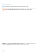
2 Tecnologia e componentes DDR4 DDR4 (double data rate fourth generation) memory is a higher-speed successor to the DDR2 and DDR3 technologies and allows up to 512 GB in capacity, compared to the DDR3's maximum of 128 GB per DIMM. DDR4 synchronous dynamic random-access memory is keyed differently from both SDRAM and DDR to prevent the user from installing the wrong type of memory into the system. DDR4 needs 20 percent less or just 1.2 volts, compared to DDR3 which requires 1.
Figure 3. Curved edge Memory Errors Memory errors on the system display the new ON-FLASH-FLASH or ON-FLASH-ON failure code. If all memory fails, the LCD does not turn on. Troubleshoot for possible memory failure by trying known good memory modules in the memory connectors on the bottom of the system or under the keyboard, as in some portable systems. NOTE: The DDR4 memory is imbedded in board and not a replaceable DIMM as shown and referred.
Velocidade Atualmente, existem 3 modos de velocidade definidos pela especificação mais recente USB 3.0/USB 3.1 Geração 1. São elas a Super Velocidade (Super-Speed), Alta Velocidade (Hi-Speed) e Full-Speed (Velocidade Total). O novo modo SuperSpeed tem uma taxa de transferência de 4,8 Gbps. Apesar de as especificações reterem os modos USB Hi-Speed e Full-Speed, comummente conhecidos como USB 2.0 e 1.
Compatibilidade A boa notícia é que o USB 3.0/USB 3.1 Geração 1 tem sido bastante bem planeado desde o início para coexistir pacificamente com o USB 2.0. Antes de mais, apesar de o USB 3.0/USB 3.1 Geração 1 especificar novas ligações físicas e, portanto, novos cabos, para tirar partido da maior velocidade do novo protocolo, o próprio conector permanece igual, com a mesma forma retangular e os quatro contactos USB 2.0, encontrando-se exatamente no mesmo local que anteriormente.
Table 2. Intel Optane memory specifications Feature Specifications Interface PCIe 3x2 NVMe 1.1 Connector M.2 card slot (2230/2280) Configurations supported • • • Capacity 32 GB or 64 GB 7th Generation or higher Intel Core i3/i5/i7 processor Windows 10 64-bit version or higher Intel Rapid Storage Technology driver version 15.9.1.1018 or higher Ativar a memória Intel Optane Passo 1. Na barra de tarefas, clique na caixa de pesquisa e escreva "Intel Rapid Storage Technology". 2.
Intel UHD Graphics 620 Estimated Maximum Power Consumption (TDP) 15 W (included in the CPU power) Overlay Planes Yes Operating Systems Graphics/ Video API Support DirectX 12 (Windows 10), OpenGL 4.5 Maximum Vertical Refresh Rate Up to 85 Hz depending on resolution Multiple Display Support On System: eDP (internal), HDMI Via Optional USB Type-C Port: VGA, DisplayPort External Connectors HDMI 1.4b USB Type–C port Equivalente a Nvidia GeForce MX130 Tabela 4.
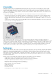
3 Major components of your system 1. Base cover 2.
3. 4. 5. 6. 7. 8. 9. 10. 11. 12. 13. 14. 15. 16. WLAN card Memory modules System board M.2 Solid-state drive or Intel Optane memory—Optional Battery Palmrest assembly Speakers Touchpad assembly Display assembly Hard drive assembly IO board VGA daughterboard System fan Heatsink NOTE: Dell provides a list of components and their part numbers for the original system configuration purchased. These parts are available according to warranty coverages purchased by the customer.
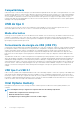
4 Retirar e instalar componentes Ferramentas recomendadas Os procedimentos descritos neste documento requerem as seguintes ferramentas: • • • Chave de parafusos Phillips #0 Chave de parafusos Phillips #1 Instrumento de plástico pontiagudo NOTA: A chave de parafusos n.º 0 é para parafusos 0-1 e a chave de parafusos n.º 1 é para parafusos 2-4. Cartão SD (Secure Digital) Retirar o cartão Secure Digital Pré-requisitos 1. Siga o procedimento indicado em Antes de trabalhar no interior do computador. Passo 1.
Instalar o cartão Secure Digital Passo 1. Faça deslizar o cartão Secure Digital para dentro do encaixe até encaixar no lugar no um estalo. 2. Siga os procedimentos indicados em Após efetuar qualquer procedimento no interior do computador. Tampa da base Retirar a tampa da base Pré-requisitos 1. Siga o procedimento indicado em antes de trabalhar no interior do computador. 2. Retire a placa de memória SD Passo 1.
2. Abra a tampa da base e continue para abrir o lado direito da tampa da base.
3. Levante o lado direito da tampa da base [1], e retire-a do conjunto do teclado e apoio para as mãos [2]. Instalar a tampa da base Passo 1. Coloque a tampa da base no conjunto do teclado e descanso para as mãos [1].
2. Aperte os nove parafusos integrados que fixam a tampa da base ao conjunto do teclado e descanso para as mãos.
Passos seguintes 1. Volte a colocar a placa de memória SD 2. Siga o procedimento indicado em Após efetuar qualquer procedimento no interior do computador Bateria Precauções com a bateria de iões de lítio AVISO: • Tenha todo o cuidado quando manusear as baterias de iões de lítio. • Descarregue a bateria o máximo possível antes de a remover do sistema. Isto pode ser realizado desligando o adaptador de CA do sistema para permitir gastar a bateria.
2. Retire os quatro parafusos (M2x3) que fixam a bateria ao conjunto do teclado e descanso para as mãos [1]. 3. Levante a bateria do conjunto do teclado e descanso para as mãos [2].
Instalar a bateria Passo 1. Alinhe os orifícios dos parafusos na bateria com os orifícios dos parafusos no conjunto do teclado e descanso para as mãos [1]. 2. Volte a colocar os quatro parafusos (M2x3) que fixam a bateria ao conjunto do teclado e descanso para as mãos [2].
3. Ligue o cabo da bateria à placa de sistema.
Passos seguintes 1. Volte a colocar a tampa da base 2. Volte a colocar a placa de memória SD 3. Siga o procedimento indicado em Após efetuar qualquer procedimento no interior do computador Disco rígido Removing the hard drive assembly Prerequisites 1. 2. 3. 4. Follow the procedure in before working inside your computer Remove the SD memory card Remove the base cover Disconnect the battery cable. Steps 1. Disconnect the hard drive cable from the system board [1]. 2.
Installing the hard drive assembly Steps 1. Align the screw holes on the hard drive assembly with the screw holes on the palm rest and keyboard assembly [1]. 2. Replace the four (M2x4.5) screws that secure the hard drive assembly to the palm rest and keyboard assembly [2].
3. Adhere the tape that secures the hard drive cable to the system board [1]. 4. Connect the hard drive cable to the system board [2].
Next steps 1. 2. 3. 4. Replace the battery cable. Replace the base cover Replace the SD memory card Follow the procedure in after working inside your computer Placa de E/S Removing the IO board Prerequisites 1. 2. 3. 4. 5. Follow the procedure in before working inside your computer. Remove the SD memory card. Remove the base cover. Remove the battery. Remove the hard drive assembly. NOTE: Required for systems with 42 Whr battery Steps 1.
Installing the IO board Steps 1. Using the alignment posts, place the I/O board on the palm rest and keyboard assembly [1]. 2. Replace the two (M2x3) screws that secure the I/O board to the palm rest and keyboard assembly [2].
3. Adhere the I/O board cable to the palm rest and keyboard assembly [1]. 4. Connect the I/O board cable to the system board and close the latch to secure the cable [2].
Next steps 1. Replace the hard drive assembly. NOTE: Required for systems with 42 Whr battery 2. 3. 4. 5. Replace the battery. Replace the base cover. Replace the SD memory card. Follow the procedure in after working inside your computer. Painel tátil Removing the touchpad assembly Prerequisites NOTE: For information only, touchpad is included with the palmrest assembly. 1. 2. 3. 4. Follow the procedure in before working inside your computer. Remove the SD memory card. Remove the base cover.
5. Remove the four (M2x2) screws that secure the touchpad to the palmrest and keyboard assembly [1]. 6. Lift the touchpad off the palmrest and keyboard assembly [2].
Instalar o conjunto da mesa sensível ao toque Sobre esta tarefa NOTA: Certifique-se de que a mesa sensível ao toque está alinhada com as guias disponíveis no conjunto do teclado e descanso para as mãos e que o espaço em ambos os lados da mesa sensível ao toque é igual. Passo 1. Coloque a mesa sensível ao toque na ranhura do conjunto do teclado e descanso para as mãos [1]. 2. Volte a colocar os quatro parafusos (M2x2) que fixam a mesa sensível ao toque ao conjunto do teclado e descanso para as mãos [2]. 3.
5. Coloque o suporte da mesa sensível ao toque na ranhura do conjunto do teclado e descanso para as mãos [1]. 6. Volte a colocar os três parafusos (M2x2) que ficam o suporte da mesa sensível ao toque ao conjunto do teclado e descanso para as mãos [2], e cole a fita que fixa o suporte à mesa sensível ao toque.
Passos seguintes 1. 2. 3. 4. Volte a colocar a bateria Volte a colocar a tampa da base Volte a colocar a placa de memória SD Siga o procedimento indicado em Após efetuar qualquer procedimento no interior do computador Módulos de memória Removing the memory module Prerequisites 1. 2. 3. 4. Follow the procedure in before working inside your computer Remove the SD memory card Remove the base cover Disconnect the battery cable. Steps 1.
NOTE: If you do not hear the click, remove the memory module and reinstall it. Next steps 1. 2. 3. 4. Replace the battery cable. Replace the base cover Replace the SD memory card Follow the procedure in after working inside your computer SIM Card Removing the SIM card Prerequisites 1. Follow the procedure in Before working inside your computer Steps 1. Open the latch that covers the SIM card slot to release it from the system [1]. 2. Insert a needle in the slot and push it to eject the SIM card tray [2].
Installing the SIM card Steps 1. Open the latch that covers the SIM card slot to release it from the system [1]. 2. Insert a needle in the slot and push it to eject the SIM card tray [2]. 3. Pull the SIM card try and place the SIM card on the SIM cad tray [3] and [4]. 4. Slide the SIM card tray into the slot until it clicks into place.
5. Follow the procedures in After working inside your computer. placa WLAN Removing the WLAN card Prerequisites 1. 2. 3. 4. Follow the procedure in before working inside your computer Remove the SD memory card Remove the base cover Disconnect the battery cable. Steps 1. Remove the single (M2x3) screw that secures the WLAN card bracket to the system board [1]. 2. Slide and remove the WLAN card bracket that secures the WLAN cables [2]. 3. Disconnect the WLAN cables from the connectors on the WLAN card [3].
Installing the WLAN card About this task CAUTION: To avoid damage to the WLAN card, do not place any cables under it. Steps 1. Insert the WLAN card into the connector on the system board [1]. 2. Connect the WLAN cables to the connectors on the WLAN card [2]. 3. Place the WLAN card bracket to secure the WLAN cables to the WLAN card [3]. 4. Replace the single (M2x3) screw to secure the WLAN bracket to the WLAN card [4].
Next steps 1. 2. 3. 4. Disconnect the battery cable. Replace the base cover. Replace the SD memory card. Follow the procedure in after working inside your computer. Unidade de estado sólido/módulo de memória Intel Optane Removing the M.2 2280 Solid-state drive or Intel Optane memory— Optional Prerequisites NOTE: Disable the Intel Optane memory before removing the Intel Optane memory module from your computer.
3. Slide and remove the thermal plate from the solid-state drive/Intel Optane card slot [3]. 4. Remove the single (M2x2) screw that secures the solid-state drive/Intel Optane card to the palmrest and keyboard assembly [1]. 5. Slide and lift the solid-state drive/Intel Optane card off the palmrest and keyboard assembly [2].
Installing the M.2 2280 Solid-state drive or Intel Optane memory Optional Steps 1. Slide and insert the tab solid-state drive/Intel Optane card into the solid-state drive/Intel Optane card slot [1]. 2. Replace the single (M2x2) screw that secures the solid-state drive/Intel Optane card to the palmrest and keyboard assembly [2].
Retirar e instalar componentes
3. Align and replace the thermal plate on the solid-state drive/Intel Optane card slot [1,2]. 4. Replace the single (M2x3) screw that secures the thermal plate to the palmrest and keyboard assembly [3]. Next steps 1. 2. 3. 4. Replace the battery cable. Replace the base cover Replace the SD memory card Follow the procedure in after working inside your computer Removing the M.2 Solid-state drive bracket Prerequisites 1. 2. 3. 4.
Installing the Solid-state drive bracket Steps 1. Align and replace the solid-state drive bracket on the palmrest and keyboard assembly [1]. 2. Replace the single (M2x3) screw that secures the solid-state drive bracket to the palmrest and keyboard assembly [2].
Next steps 1. 2. 3. 4. Replace the battery cable. Replace the base cover Replace the SD memory card Follow the procedure in after working inside your computer Removing the M.2 2230 Solid-state drive Prerequisites 1. 2. 3. 4. Follow the procedure in before working inside your computer Remove the SD memory card Remove the base cover Disconnect the battery cable Steps 1. Remove the single (M2x3) screw that secures the thermal plate to the palmrest and keyboard assembly [1]. 2.
4. Remove the single (M2x2) screw that secures the solid-state drive to the solid-state drive bracket [1]. 5. Slide and remove the solid-state drive off the solid-state drive slot [2].
Installing the M.2 2230 Solid-state drive Steps 1. Insert the solid-state drive into the solid-state drive slot on the system board [1]. 2. Replace the single (M2x3) screw that secures the solid-state drive to the solid-state drive bracket [2].
3. Align and replace the thermal plate on the solid-state drive [1,2]. 4. Replace the single (M2x3) screw that secures the thermal plate to the palmrest and keyboard assembly [3].
Next steps 1. 2. 3. 4. Replace the battery cable. Replace the base cover Replace the SD memory card Follow the procedure in after working inside your computer Altifalantes Removing the speakers Prerequisites 1. 2. 3. 4. Follow the procedure in before working inside your computer Remove the SD memory card Remove the base cover Disconnect the battery cable. Steps 1. Disconnect the speaker cable from the system board [1]. 2.
3. Lift the speakers, along with the cable, off the palm rest and keyboard assembly.
Installing the speakers About this task NOTE: If the rubber grommets are pushed out when removing the speakers, push them back in before replacing the speakers. Steps 1. Using the alignment posts and rubber grommets, place the speakers in the slots on the palm rest and keyboard assembly.
2. Route the speaker cable through the routing guides on the palm rest and keyboard assembly [1]. 3. Connect the speaker cable to the system board [2].
Next steps 1. 2. 3. 4. Replace the battery cable. Replace the base cover Replace the SD memory card Follow the procedure in after working inside your computer Ventoinha do sistema Removing the system fan Prerequisites 1. 2. 3. 4. Follow the procedure in before working inside your computer. Remove the SD memory card. Remove the base cover. Remove the battery. Steps 1. Disconnect the VGA board cable [1], and the display cable [2, 3] from the system board .
2. Unroute the VGA board cable and the display cable from the routing guides on the fan [1]. 3. Disconnect the fan cable from the system board [2]. 4. Remove the two (M2x3) screws that secure the fan to the palmrest and keyboard board assembly [1].
5. Lift the fan off the palmrest and keyboard board assembly [2]. Installing the system fan Steps 1. Align the screw holes on the fan with the screw holes on to the palm rest and keyboard board assembly [1]. 2. Replace the two (M2x3) screws that secure the fan to the palm rest and keyboard board assembly [2].
3. Connect the fan cable to the system board [1]. 4. Route the VGA board cable and the display cable through the routing guides on the fan [2].
5. Connect the VGA board cable [1], and the display cable [2, 3] to the system board. Next steps 1. 2. 3. 4. Replace the battery. Replace the base cover. Replace the SD memory card. Follow the procedure in after working inside your computer. Dissipador de calor Removing the heatsink—UMA Prerequisites 1. 2. 3. 4. Follow the procedure in before working inside your computer. Remove the SD memory card. Remove the base cover. Remove the battery. Steps 1.
Instalar o dissipador de calor – UMA Passo 1. Coloque o dissipador de calor na placa de sistema e alinhe os orifícios dos parafusos no dissipador de calor com os orifícios dos parafusos na placa de sistema [1]. 2. Por ordem sequencial (como indicado no dissipador de calor), aperte os sete parafusos integrados que fixam o dissipador de calor à placa de sistema [2].
Passos seguintes 1. 2. 3. 4. Volte a colocar a bateria Volte a colocar a tampa da base Volte a colocar a placa de memória SD Siga o procedimento indicado em Após efetuar qualquer procedimento no interior do computador Retirar o dissipador de calor – dedicado Pré-requisitos 1. 2. 3. 4. Siga o procedimento indicado em antes de trabalhar no interior do computador. Retire a placa de memória SD Retire a tampa da base Retire a bateria Passo 1.
Instalar o dissipador de calor – dedicado Passo 1. Coloque o dissipador de calor na placa de sistema e alinhe os orifícios dos parafusos no dissipador de calor com os orifícios dos parafusos na placa de sistema [1]. 2. Por ordem sequencial (como indicado no dissipador de calor), aperte os sete parafusos integrados que fixam o dissipador de calor à placa de sistema [2].
Passos seguintes 1. 2. 3. 4. Volte a colocar a bateria Volte a colocar a tampa da base Volte a colocar a placa de memória SD Siga o procedimento indicado em Após efetuar qualquer procedimento no interior do computador Placa secundária VGA Removing the VGA daughterboard Prerequisites 1. 2. 3. 4. Follow the procedure in before working inside your computer. Remove the SD memory card. Remove the base cover. Remove the battery. Steps 1. Disconnect the VGA daughterboard cable from the system board [1]. 2.
3. Remove the two (M2x3) screws that secure the VGA daughterboard to the palmrest and keyboard assembly [1]. 4. Lift the VGA daughterboard away from the system [2].
Instalar a placa secundária VGA Passo 1. Instale a placa secundária VGA e alinhe os respetivos orifícios dos parafusos com os orifícios dos parafusos do conjunto do teclado e descanso para as mãos [1]. 2. Volte a colocar os dois parafusos (M2x3) que fixam a placa secundária VGA no conjunto do teclado e descanso para as mãos [2]. 3. Encaminhe o cabo da placa VGA através das guias de encaminhamento na ventoinha [1] e depois ligue o cabo da placa secundária VGA à placa de sistema [2].
Passos seguintes 1. 2. 3. 4. Volte a colocar a bateria Volte a colocar a tampa da base Volte a colocar a placa de memória SD Siga o procedimento indicado em Após efetuar qualquer procedimento no interior do computador Placa do botão de energia Removing the power button board with optional fingerprint reader Prerequisites 1. 2. 3. 4. 5. 6. Follow the procedure in before working inside your computer. Remove the SD memory card. Remove the base cover. Remove the battery. Remove the system fan.
4. Remove the single (M2x3) screw that secures the power button board to the palmrest and keyboard assembly [1]. 5. Lift the power button board, along with the cable off the palmrest and keyboard assembly [2].
Installing the power button board with optional fingerprint reader Steps 1. Place the power-button board into the slot on the palmrest and keyboard assembly [1]. 2. Replace the single (M2x3) screw that secures the power button board to the palmrest and keyboard assembly [2]. 3. Affix the conductive tape to the power button board [1]. 4. Affix the power button cable to the palmrest and keyboard assembly [2]. 5.
Next steps 1. 2. 3. 4. 5. 6. Replace the display assembly. Replace the system fan. Replace the battery. Replace the base cover. Replace the SD memory card. Follow the procedure in after working inside your computer. Placa de sistema Removing the system board Prerequisites 1. 2. 3. 4. 5. 6. 7. 8. 9. 10. Follow the procedure in before working inside your computer. Remove the SD memory card. Remove the base cover. Remove the battery. Remove the WLAN. Remove the Memory. Remove the SSD. Remove the system fan.
a) b) c) d) e) Power button board [1]. Fingerprint reader (optional) [2]. IO board [3]. Touchpad [4]. Keyboard [5]. 2. Disconnect the following cables from the system board: a) DC-in [1, 2]. b) Speaker [3].
3. Remove the three (M2x3) screws and two (M2x2) screws that secure the system board to the palmrest and keyboard assembly [1]. 4. Lift the system board off the palm-rest and keyboard assembly [2].
Installing the system board Steps 1. Align the screw hole on the system board with the screw hole on the palmrest and keyboard assembly [1]. 2. Replace the three (M2x3) screws and two (M2x2) screws that secure the system board to the palmrest and keyboard assembly [2].
3. Connect the following cables to the system board: a) DC-in [1, 2]. b) Speaker [3].
4. Connect the following cables to the system board: a) b) c) d) e) 72 Power button board [1]. Fingerprint reader (optional) [2]. IO board [3]. Touchpad [4]. Keyboard [5].
Next steps 1. 2. 3. 4. 5. 6. 7. 8. 9. 10. Replace the display assembly. Replace the heatsink. Replace the system fan. Replace the SSD. Replace the Memory. Replace the WLAN. Replace the battery. Replace the base cover. Replace the SD memory card. Follow the procedure in after working inside your computer. Conjunto do ecrã Removing the display assembly Prerequisites 1. 2. 3. 4. 5. Follow the procedure in before working inside your computer. Remove the SD memory card. Remove the base cover.
3. Unroute the display cable from the routing guides on the palmrest and keyboard assembly [1]. 4. Remove the six (M2.5x5) screws that secure the left and right hinges to the system board, and palmrest and keyboard assembly [2].
5. Lift the palmrest and keyboard assembly at an angle [1]. 6. Continue to lift the palmrest and keyboard assembly until it separates from the hinges [2].
7. Slide and remove the palmrest and keyboard assembly off the display assembly.
8. After performing all the preceding steps, you are left with display assembly. Installing the display assembly About this task NOTE: Ensure that the hinges are opened to the maximum before replacing the display assembly on the palmrest and keyboard assembly. Steps 1. Align and place the palmrest and keyboard assembly under the hinges on the display assembly.
2. Press the hinges down on the system board, and palmrest and keyboard assembly [1]. 3. Seat the palmrest and keyboard assembly on the display assembly [2].
4. Replace the six (M2.5x5) screws that secure the left and right hinges to the system board, and palmrest and keyboard assembly [1]. 5. Route the display cable through the routing guides on the palmrest and keyboard assembly [2].
6. Affix the antenna cables to the system board [1]. 7. Connect the display cable to the connector on the system board [2].
Next steps 1. 2. 3. 4. 5. Replace the WLAN. Replace the battery. Replace the base cover. Replace the SD memory card. Follow the procedure in after working inside your computer. Moldura do ecrã Retirar a moldura do ecrã Pré-requisitos 1. 2. 3. 4. 5. 6. Siga o procedimento indicado em antes de trabalhar no interior do computador. Retire a placa de memória SD Retire a tampa da base Retire a bateria Retire a WLAN Retire o conjunto do ecrã Passo 1.
3. Levante a moldura do ecrã para a retirar do conjunto do ecrã.
Instalar a moldura do ecrã Passo 1. Alinhe a moldura do ecrã com a tampa posterior do mesmo.
2. Encaixe suavemente a moldura do ecrã no lugar com um estalo.
Passos seguintes 1. 2. 3. 4. 5. 6. Volte a colocar o conjunto do ecrã Volte a colocar a WLAN Volte a colocar a bateria Volte a colocar a tampa da base Volte a colocar a placa de memória SD Siga o procedimento indicado em Após efetuar qualquer procedimento no interior do computador Painel do ecrã Retirar o painel do ecrã Pré-requisitos 1. 2. 3. 4. 5. 6. 7. Siga o procedimento indicado em antes de trabalhar no interior do computador.
3. Retire a fita que fixa o cabo do ecrã à parte posterior do painel do ecrã [1]. 4. Levante o trinco e desligue o cabo do ecrã do conector do cabo do painel do ecrã [2]. 5. Levante o painel do ecrã para fora da tampa posterior do ecrã [3].
NOTA: Não puxe e solte as fitas de estiramento (SR) do painel do ecrã. Não há necessidade de separar os suportes do painel do ecrã. 6. Depois de efetuar todos os passos anteriores, resta o painel do ecrã.
Instalar o painel do ecrã Passo 1. Coloque o painel do ecrã numa superfície plana e limpa.
2. Ligue o cabo do ecrã ao conector que se encontra na parte posterior do painel do ecrã e prima o trinco para prender o cabo [1]. 3. Cole a fita que fixa o cabo do ecrã à parte posterior do painel do ecrã [2]. 4. Vire o painel do ecrã ao contrário e coloque-o sobre a tampa posterior do ecrã [3].
5. Alinhe os orifícios dos parafusos no painel do ecrã com os orifícios dos parafusos na tampa posterior do ecrã [1]. 6. Volte a colocar os seis parafusos (M2x2) e os dois parafusos (M2x3) que fixam o painel do ecrã à tampa posterior do ecrã [2].
Passos seguintes 1. 2. 3. 4. 5. 6. 7. Volte a colocar a moldura do ecrã. Volte a colocar o conjunto do ecrã. Volte a colocar a WLAN Volte a colocar a bateria Volte a colocar a tampa da base Volte a colocar a placa de memória SD Siga o procedimento indicado em Após efetuar qualquer procedimento no interior do computador Cabo do ecrã Remover o cabo do ecrã Pré-requisitos 1. 2. 3. 4. 5. 6. 7. 8. Siga o procedimento indicado em antes de trabalhar no interior do computador.
Passo 1. Retire o cabo da câmara e o cabo do ecrã das guias de encaminhamento na tampa posterior do ecrã [1, 2]. 2. Retire a fita adesiva que fixa o cabo da câmara [3]. 3. Levante o cabo da câmara e o cabo do ecrã retirando-os da tampa posterior do ecrã.
Instalar o cabo do ecrã Passo 1. Coloque o cabo do ecrã e o cabo da câmara na tampa posterior do ecrã.
2. Encaminhe o cabo do ecrã e o cabo da câmara ao longo das guias de encaminhamento no conjunto da antena e tampa posterior do ecrã [1, 2]. 3. Cole a fita adesiva que fixa o cabo da câmara [3].
Passos seguintes 1. 2. 3. 4. 5. 6. 7. 8. Volte a colocar o painel do ecrã Volte a colocar a moldura do ecrã Volte a colocar o conjunto do ecrã Volte a colocar a WLAN Volte a colocar a bateria Volte a colocar a tampa da base Volte a colocar a placa de memória SD Siga o procedimento indicado em Após efetuar qualquer procedimento no interior do computador Porta do transformador de corrente Removing the power adapter port Prerequisites 1. 2. 3. 4. 5.
Instalar a porta do transformador Passo 1. Coloque a porta do adaptador elétrico na ranhura do conjunto do teclado e descanso para as mãos [1]. 2. Volte a colocar o único parafuso (M2x3) que fixa a porta do adaptador elétrico ao conjunto do teclado e descanso para as mãos [2]. 3. Ligue o cabo do adaptador de energia à placa de sistema [3, 4].
Passos seguintes 1. 2. 3. 4. 5. Volte a colocar a WLAN Volte a colocar a bateria Volte a colocar a tampa da base Volte a colocar a placa de memória SD Siga o procedimento indicado em Após efetuar qualquer procedimento no interior do computador Câmara Removing the camera Prerequisites 1. 2. 3. 4. 5. 6. 7. 8.
Follow the below procedure to remove the camera in systems with the Touch functionality. 4. Peel the tape that secures the camera off the display back-cover [1]. 5. Lift the camera module from the display back-cover [2].
Installing the camera Steps 1. Connect the camera cable to the camera module [1]. 2. Route the camera cable through the routing channels [2]. 3. Using the alignment post, adhere the camera module on the display back-cover [3].
Following is the procedure to install the camera in systems with the Touch functionality. 4. Align and replace the camera module on the display back-cover [1]. 5. Adhere the tape that secures the camera off the display back-cover [2].
Next steps 1. 2. 3. 4. 5. 6. 7. 8. Replace the display panel. Replace the display bezel. Replace the display assembly. Replace the WLAN. Replace the battery. Replace the base cover. Replace the SD memory card. Follow the procedure in after working inside your computer. Conjunto do teclado e apoio para as mãos Removing the palmrest and keyboard assembly Prerequisites 1. 2. 3. 4. 5. 6. 7. 8. 9.
10. 11. 12. 13. 14. 15. 16. 17. Remove the touch pad assembly Remove the VGA daughter board Remove the power button board Remove the speakers Remove the system fan Remove the heatsink Remove the system board Remove the display assembly About this task After performing the preceding steps, you are left with the palmrest and keyboard assembly. NOTE: The power button board is not included with the service replacement palmrest assembly.
5 Troubleshooting Diagnóstico de avaliação otimizada do sistema préarranque - Diagnóstico ePSA Sobre esta tarefa O diagnóstico ePSA (também conhecido como diagnóstico do sistema) efetua uma verificação completa do hardware. O ePSA está integrado no BIOS e é iniciado internamente pelo BIOS. O diagnóstico de sistema integrado fornece um conjunto de opções para dispositivos específicos ou grupos de dispositivos que permite: O diagnóstico ePSA pode ser iniciado pelos botões FN+PWR enquanto liga o computador.
Diagnóstico Tabela 5. Diagnóstico M-BIST L-BIST Finalidade da ferramenta de diagnóstico Avalia o estado da placa de sistema para ter outras soluções para sintomas de "Sem energia", "Sem post" e "Sem vídeo" e para reduzir as emissões repetidas. Verifica se a placa de sistema está a fornecer energia ao ecrã LCD, realizando um teste de trilho de energia ao LCD, o que permite o isolamento do sintoma "Sem vídeo" para a placa principal, LCD ou cabo.
The system will not shut down when displaying the Diagnostic Error Codes. Diagnostic Error Codes always supersede any other use of the LED. For instance, on Notebooks, battery codes for Low Battery or Battery Failure situations will not be displayed when Diagnostic Error Codes are being displayed. Table 6. Diagnostic LED Blinking Pattern Possible Problem Suggested Resolution 1 CPU failure Replace the system board.
6 Obter ajuda Contactar a Dell Pré-requisitos NOTA: Se não tiver uma ligação activa à Internet, poderá encontrar as informações de contacto na sua factura, na nota de encomenda ou no catálogo de produtos Dell. Sobre esta tarefa A Dell disponibiliza várias opções de serviço e assistência através da Internet e de telefone. A disponibilidade varia de acordo com o país e o produto, e alguns serviços podem não estar disponíveis na sua área.