Dell Latitude 3400 Service Manual Regulatory Model: P111G Regulatory Type: P111G001
Anmärkningar, försiktighetsbeaktanden och varningar OBS OBS innehåller viktig information som hjälper dig att få ut det mesta av produkten. CAUTION VIKTIGT anger antingen risk för skada på maskinvara eller förlust av data och förklarar hur du kan undvika problemet. VARNING En VARNING visar på en potentiell risk för egendoms-, personskador eller dödsfall. © 2019 Dell Inc. eller dess dotterbolag. Med ensamrätt. Dell, EMC och andra varumärken är varumärken som tillhör Dell Inc. eller dess dotterbolag.
Contents 1 Arbeta med datorn........................................................................................................................5 Säkerhetsinstruktioner.......................................................................................................................................................... 5 Stänga av datorn – Windows 10..........................................................................................................................................
5 Troubleshooting........................................................................................................................103 Förbättrad systemutvärderingsdiagnostik före start, ePSA-diagnostik......................................................................103 Köra ePSA-diagnostiken..............................................................................................................................................103 Diagnostik....................................................
1 Arbeta med datorn Säkerhetsinstruktioner Förutsättningar Följ dessa säkerhetsföreskrifter för att skydda datorn och dig själv. Om inget annat anges förutsätts i varje procedur i det här dokumentet att följande villkor har uppfyllts: • • Du har läst säkerhetsinformationen som medföljde datorn. En komponent kan ersättas eller – om du köper den separat – monteras i omvänd ordning jämfört med borttagningsproceduren.
OBS Kontrollera att datorn och alla anslutna enheter är avstängda. Om datorn eller någon ansluten enhet inte stängdes av automatiskt när du stängde av operativsystemet trycker du ned strömknappen i 6 sekunder för att stänga av dem. Innan du arbetar inuti datorn Om denna uppgift För att undvika att skada datorn ska du utföra följande åtgärder innan du börjar arbeta i den. Steg 1. Se till att följa Säkerhetsinstruktionerna. 2. Se till att arbetsytan är ren och plan så att inte datorkåpan skadas. 3.
2 Teknik och komponenter DDR4 DDR4 (double data rate fourth generation) memory is a higher-speed successor to the DDR2 and DDR3 technologies and allows up to 512 GB in capacity, compared to the DDR3's maximum of 128 GB per DIMM. DDR4 synchronous dynamic random-access memory is keyed differently from both SDRAM and DDR to prevent the user from installing the wrong type of memory into the system. DDR4 needs 20 percent less or just 1.2 volts, compared to DDR3 which requires 1.
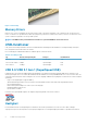
Figure 3. Curved edge Memory Errors Memory errors on the system display the new ON-FLASH-FLASH or ON-FLASH-ON failure code. If all memory fails, the LCD does not turn on. Troubleshoot for possible memory failure by trying known good memory modules in the memory connectors on the bottom of the system or under the keyboard, as in some portable systems. NOTE: The DDR4 memory is imbedded in board and not a replaceable DIMM as shown and referred. USB-funktioner USB (Universal Serial Bus) lanserades 1996.
fortfarande USB-lägena Hi-Speed och Full-Speed, eller vad som brukar kallas USB 2.0 och USB 1.1. Dessa lägen är fortfarande långsammare (480 Mbit/s respektive 12 Mbit/s), men finns kvar för att säkerställa bakåtkompatibilitet. USB 3.0/USB 3.1 Gen 1 ger en mycket högre prestanda tack vare följande tekniska förändringar: • • • En ytterligare fysisk buss har lagts till parallellt med den befintliga USB 2.0-bussen (se bilden nedan). USB 2.
3.0/USB 3.1 Gen 1-kablarna finns fem nya kontakter för oberoende mottagning och sändning av data som endast fungerar när de ansluts till en riktig SuperSpeed USB-anslutning. USB Typ-C USB Type-C är en ny och liten fysisk kontakt. Själva kontakten ger stöd för olika spännande nya USB-standarder som USB 3.1 och USB Power Delivery (USB-PD). Alternativt läge USB Type-C är en ny kontaktstandard som är mycket liten. Den är ungefär en tredjedel så stor som en gammal USB Type-A-kontakt.
Feature Specifications Capacity 32 GB or 64 GB Aktivera Intel Optane-minne Steg 1. I aktivitetsfältet ska du klickar på sökrutan och skriva "Intel Rapid Storage Technology". 2. Klicka på Intel Rapid Storage Technology. 3. På fliken Status ska du klicka på Aktivera för att aktivera Intel Optane-minnet. 4. På varningsskärmen ska du välja en kompatibel enhet snabbt och sedan klicka på Ja för att fortsätta aktivera Intel Optane-minnet. 5.
Intel UHD Graphics 620 USB Type–C port Nvidia GeForce MX130 motsvarande Tabell 4. Nvidia GeForce MX130 specifikationer Funktion Specifikationer Grafikminne 2 GB GDDR5 Busstyp PCI Express 3.0 Minnesgränssnitt GDDR5 Klockhastigheter 1122 - 1242 (Boost) MHz Maximalt färgdjup e.t. Maximal vertikal uppdateringsfrekvens e.t. Operativsystem grafik/video API Support Windows 10/ DX 12/ OGL4.5 Uppdaterade lösningar och Max Refresh Rates (Hz) e.t.
3 Major components of your system 1. Base cover 2.
3. 4. 5. 6. 7. 8. 9. 10. 11. 12. 13. 14. 15. 16. WLAN card Memory modules System board M.2 Solid-state drive or Intel Optane memory—Optional Battery Palmrest assembly Speakers Touchpad assembly Display assembly Hard drive assembly IO board VGA daughterboard System fan Heatsink NOTE: Dell provides a list of components and their part numbers for the original system configuration purchased. These parts are available according to warranty coverages purchased by the customer.
4 Ta bort och installera komponenter Recommended tools The procedures in this document require the following tools: • • • Phillips #0 screwdriver Phillips #1 screwdriver Plastic scribe NOTE: The #0 screw driver is for screws 0-1 and the #1 screw driver is for screws 2-4. SD-kort (Secure Digital) Ta bort SD-kortet (Secure digital) Förutsättningar 1. Följ proceduren i Innan du arbetar inuti datorn. Steg 1. Tryck på-SD-kortet för att lossa det från datorn. 2. För ut-SD-kortet från datorn.
Installera SD-kortet (Secure Digital) Steg 1. För in-SD-kortet i kortplatsen tills det klickar på plats. 2. Följ anvisningarna i När du har arbetat inuti datorn. Kåpan Ta bort kåpan Förutsättningar 1. Följ anvisningarna i innan du arbetar inuti datorn. 2. Ta bort SD-minneskortet Steg 1. Lossa de nio fästskruvarna som sätter fast baslocket på handledsstödet och tangentbordet.
2. Bänd baslocket och fortsätt att öppna höger sida på baslocket.
3. Lyft höger sida på baslocket [1] och ta av det från handledsstödet och tangentbordet [2]. Installera kåpan Steg 1. Placera baskåpan på handledsstöds- och tangentbordsenheten [1].
2. Dra åt de nio fästskruvarna som sätter fast baslocket på handledsstödet och tangentbordet.
Nästa Steg 1. Sätt tillbaka SD-minneskortet 2. Följ proceduren i när du har arbetat inuti datorn. Batteri Försiktighetsåtgärder gällande litiumjonbatterier CAUTION • Var försiktig när du hanterar litiumjonbatterier. • Ladda ur batteriet så mycket som möjligt innan du tar bort det från datorn. Detta kan göras genom att koppla bort nätadaptern från systemet för att låta batteriet laddas ur. • Undvik att krossa, tappa, skada eller tränga in i batteriet med främmande föremål.
2. Ta bort de fyra skruvarna (M2x3) som håller fast batteriet i handledsstöds- och tangentbordsenheten [1]. 3. Lyft av batteriet från handledsstöds- och tangentbordsenheten [2].
Installera batteriet Steg 1. Rikta in skruvhålen på batteriet med skruvhålen på handledsstöds- och tangentbordsenheten [1]. 2. Sätt tillbaka de fyra skruvarna (M2x3) som håller fast batteriet i handledsstöds- och tangentbordsenheten [2].
3. Anslut batterikabeln till moderkortet.
Nästa Steg 1. Sätt tillbaka baskåpan 2. Sätt tillbaka SD-minneskortet 3. Följ proceduren i när du har arbetat inuti datorn. Hårddisk Removing the hard drive assembly Prerequisites 1. 2. 3. 4. Follow the procedure in before working inside your computer Remove the SD memory card Remove the base cover Disconnect the battery cable. Steps 1. Disconnect the hard drive cable from the system board [1]. 2. Peel the tape that secures the hard drive cable to the system board [2]. 3. Remove the four (M2x4.
Installing the hard drive assembly Steps 1. Align the screw holes on the hard drive assembly with the screw holes on the palm rest and keyboard assembly [1]. 2. Replace the four (M2x4.5) screws that secure the hard drive assembly to the palm rest and keyboard assembly [2].
3. Adhere the tape that secures the hard drive cable to the system board [1]. 4. Connect the hard drive cable to the system board [2].
Next steps 1. 2. 3. 4. Replace the battery cable. Replace the base cover Replace the SD memory card Follow the procedure in after working inside your computer I/O-kort Removing the IO board Prerequisites 1. 2. 3. 4. 5. Follow the procedure in before working inside your computer. Remove the SD memory card. Remove the base cover. Remove the battery. Remove the hard drive assembly. NOTE: Required for systems with 42 Whr battery Steps 1.
Installing the IO board Steps 1. Using the alignment posts, place the I/O board on the palm rest and keyboard assembly [1]. 2. Replace the two (M2x3) screws that secure the I/O board to the palm rest and keyboard assembly [2].
3. Adhere the I/O board cable to the palm rest and keyboard assembly [1]. 4. Connect the I/O board cable to the system board and close the latch to secure the cable [2].
Next steps 1. Replace the hard drive assembly. NOTE: Required for systems with 42 Whr battery 2. 3. 4. 5. Replace the battery. Replace the base cover. Replace the SD memory card. Follow the procedure in after working inside your computer. Pekskiva Removing the touchpad assembly Prerequisites NOTE: For information only, touchpad is included with the palmrest assembly. 1. 2. 3. 4. Follow the procedure in before working inside your computer. Remove the SD memory card. Remove the base cover.
5. Remove the four (M2x2) screws that secure the touchpad to the palmrest and keyboard assembly [1]. 6. Lift the touchpad off the palmrest and keyboard assembly [2].
Installera styrplattenheten Om denna uppgift OBS Se till att pekplattan är inriktad med hållarna som finns tillgängliga på enheten med handledsstöd och tangentbordet och att avståndet på båda sidor om pekplattan är det samma. Steg 1. Placera styrplattan i facket på handledsstöds- och tangentbordsenheten [1] 2. Sätt tillbaka de fyra skruvarna (M2x2) som håller fast styrplattan på handledsstöds- och tangentbordsenheten [2]. 3.
5. Placera styrplattans fäste i facket på handledsstöds- och tangentbordsenheten [1] 6. Sätt tillbaka de tre skruvarna (M2x2) som håller fast fästet för pekskivan i handledsstöds- och tangentbordsmonteringen [2], och sätt fast tejpen som håller fast fästet i handledsstödet.
Nästa Steg 1. 2. 3. 4. Sätt tillbaka batteriet Sätt tillbaka baskåpan Sätt tillbaka SD-minneskortet Följ proceduren i när du har arbetat inuti datorn. Minnesmoduler Removing the memory module Prerequisites 1. 2. 3. 4. Follow the procedure in before working inside your computer Remove the SD memory card Remove the base cover Disconnect the battery cable. Steps 1. Pry the clips securing the memory module until the memory module pops-up [1]. 2. Remove the memory module from the memory module slot [2].
NOTE: If you do not hear the click, remove the memory module and reinstall it. Next steps 1. 2. 3. 4. Replace the battery cable. Replace the base cover Replace the SD memory card Follow the procedure in after working inside your computer SIM Card Removing the SIM card Prerequisites 1. Follow the procedure in Before working inside your computer Steps 1. Open the latch that covers the SIM card slot to release it from the system [1]. 2. Insert a needle in the slot and push it to eject the SIM card tray [2].
Installing the SIM card Steps 1. Open the latch that covers the SIM card slot to release it from the system [1]. 2. Insert a needle in the slot and push it to eject the SIM card tray [2]. 3. Pull the SIM card try and place the SIM card on the SIM cad tray [3] and [4]. 4. Slide the SIM card tray into the slot until it clicks into place.
5. Follow the procedures in After working inside your computer. WLAN-kort Removing the WLAN card Prerequisites 1. 2. 3. 4. Follow the procedure in before working inside your computer Remove the SD memory card Remove the base cover Disconnect the battery cable. Steps 1. Remove the single (M2x3) screw that secures the WLAN card bracket to the system board [1]. 2. Slide and remove the WLAN card bracket that secures the WLAN cables [2]. 3. Disconnect the WLAN cables from the connectors on the WLAN card [3].
Installing the WLAN card About this task CAUTION: To avoid damage to the WLAN card, do not place any cables under it. Steps 1. Insert the WLAN card into the connector on the system board [1]. 2. Connect the WLAN cables to the connectors on the WLAN card [2]. 3. Place the WLAN card bracket to secure the WLAN cables to the WLAN card [3]. 4. Replace the single (M2x3) screw to secure the WLAN bracket to the WLAN card [4].
Next steps 1. 2. 3. 4. Disconnect the battery cable. Replace the base cover. Replace the SD memory card. Follow the procedure in after working inside your computer. Halvledarenhet/Intel Optane-minnesmodul Removing the M.2 2280 Solid-state drive or Intel Optane memory— Optional Prerequisites NOTE: Disable the Intel Optane memory before removing the Intel Optane memory module from your computer. For more information about disabling the Intel Optane memory, see disabling Intel Optane memory 1. 2. 3. 4.
3. Slide and remove the thermal plate from the solid-state drive/Intel Optane card slot [3]. 4. Remove the single (M2x2) screw that secures the solid-state drive/Intel Optane card to the palmrest and keyboard assembly [1]. 5. Slide and lift the solid-state drive/Intel Optane card off the palmrest and keyboard assembly [2].
Installing the M.2 2280 Solid-state drive or Intel Optane memory Optional Steps 1. Slide and insert the tab solid-state drive/Intel Optane card into the solid-state drive/Intel Optane card slot [1]. 2. Replace the single (M2x2) screw that secures the solid-state drive/Intel Optane card to the palmrest and keyboard assembly [2].
Ta bort och installera komponenter
3. Align and replace the thermal plate on the solid-state drive/Intel Optane card slot [1,2]. 4. Replace the single (M2x3) screw that secures the thermal plate to the palmrest and keyboard assembly [3]. Next steps 1. 2. 3. 4. Replace the battery cable. Replace the base cover Replace the SD memory card Follow the procedure in after working inside your computer Removing the M.2 Solid-state drive bracket Prerequisites 1. 2. 3. 4.
Installing the Solid-state drive bracket Steps 1. Align and replace the solid-state drive bracket on the palmrest and keyboard assembly [1]. 2. Replace the single (M2x3) screw that secures the solid-state drive bracket to the palmrest and keyboard assembly [2].
Next steps 1. 2. 3. 4. Replace the battery cable. Replace the base cover Replace the SD memory card Follow the procedure in after working inside your computer Removing the M.2 2230 Solid-state drive Prerequisites 1. 2. 3. 4. Follow the procedure in before working inside your computer Remove the SD memory card Remove the base cover Disconnect the battery cable Steps 1. Remove the single (M2x3) screw that secures the thermal plate to the palmrest and keyboard assembly [1]. 2.
4. Remove the single (M2x2) screw that secures the solid-state drive to the solid-state drive bracket [1]. 5. Slide and remove the solid-state drive off the solid-state drive slot [2].
Installing the M.2 2230 Solid-state drive Steps 1. Insert the solid-state drive into the solid-state drive slot on the system board [1]. 2. Replace the single (M2x3) screw that secures the solid-state drive to the solid-state drive bracket [2].
3. Align and replace the thermal plate on the solid-state drive [1,2]. 4. Replace the single (M2x3) screw that secures the thermal plate to the palmrest and keyboard assembly [3].
Next steps 1. 2. 3. 4. Replace the battery cable. Replace the base cover Replace the SD memory card Follow the procedure in after working inside your computer Högtalare Removing the speakers Prerequisites 1. 2. 3. 4. Follow the procedure in before working inside your computer Remove the SD memory card Remove the base cover Disconnect the battery cable. Steps 1. Disconnect the speaker cable from the system board [1]. 2.
3. Lift the speakers, along with the cable, off the palm rest and keyboard assembly.
Installing the speakers About this task NOTE: If the rubber grommets are pushed out when removing the speakers, push them back in before replacing the speakers. Steps 1. Using the alignment posts and rubber grommets, place the speakers in the slots on the palm rest and keyboard assembly.
2. Route the speaker cable through the routing guides on the palm rest and keyboard assembly [1]. 3. Connect the speaker cable to the system board [2].
Next steps 1. 2. 3. 4. Replace the battery cable. Replace the base cover Replace the SD memory card Follow the procedure in after working inside your computer Systemfläkt Removing the system fan Prerequisites 1. 2. 3. 4. Follow the procedure in before working inside your computer. Remove the SD memory card. Remove the base cover. Remove the battery. Steps 1. Disconnect the VGA board cable [1], and the display cable [2, 3] from the system board .
2. Unroute the VGA board cable and the display cable from the routing guides on the fan [1]. 3. Disconnect the fan cable from the system board [2]. 4. Remove the two (M2x3) screws that secure the fan to the palmrest and keyboard board assembly [1].
5. Lift the fan off the palmrest and keyboard board assembly [2]. Installing the system fan Steps 1. Align the screw holes on the fan with the screw holes on to the palm rest and keyboard board assembly [1]. 2. Replace the two (M2x3) screws that secure the fan to the palm rest and keyboard board assembly [2].
3. Connect the fan cable to the system board [1]. 4. Route the VGA board cable and the display cable through the routing guides on the fan [2].
5. Connect the VGA board cable [1], and the display cable [2, 3] to the system board. Next steps 1. 2. 3. 4. Replace the battery. Replace the base cover. Replace the SD memory card. Follow the procedure in after working inside your computer. Kylfläns Removing the heatsink—UMA Prerequisites 1. 2. 3. 4. Follow the procedure in before working inside your computer. Remove the SD memory card. Remove the base cover. Remove the battery. Steps 1.
Installera kylflänsen - UMA Steg 1. Placera kylflänsen på moderkortet och rikta in skruvhålen på kylflänsen med skruvhålen på moderkortet [1]. 2. Dra åt de fyra fästskruvarna som håller fast kylflänsen i moderkortet i rätt ordning (anges på kylflänsen).
Nästa Steg 1. 2. 3. 4. Sätt tillbaka batteriet Sätt tillbaka baskåpan Sätt tillbaka SD-minneskortet Följ proceduren i när du har arbetat inuti datorn. Ta bort kylflänsen— separat Förutsättningar 1. 2. 3. 4. Följ anvisningarna i innan du arbetar inuti datorn. Ta bort SD-minneskortet Ta bort kåpan. Ta bort batteriet Steg 1. Lossa de sju fästskruvarna som håller fast kylflänsen i moderkortet [1]. OBS Lossa skruvarna i samma ordning som på bildtext nummer [1, 2, 3, 4,5,6,7] som anges på kylflänsen. 2.
Installera kylflänsen— separat Steg 1. Placera kylflänsen på moderkortet och rikta in skruvhålen på kylflänsen med skruvhålen på moderkortet [1]. 2. Dra åt de sju fästskruvarna som håller fast kylflänsen i moderkortet i rätt ordning (anges på kylflänsen) [2].
Nästa Steg 1. 2. 3. 4. Sätt tillbaka batteriet Sätt tillbaka baskåpan Sätt tillbaka SD-minneskortet Följ proceduren i när du har arbetat inuti datorn. VGA-dotterkort Removing the VGA daughterboard Prerequisites 1. 2. 3. 4. Follow the procedure in before working inside your computer. Remove the SD memory card. Remove the base cover. Remove the battery. Steps 1. Disconnect the VGA daughterboard cable from the system board [1]. 2. Unroute the VGA board cable from the routing guides on the fan [2].
3. Remove the two (M2x3) screws that secure the VGA daughterboard to the palmrest and keyboard assembly [1]. 4. Lift the VGA daughterboard away from the system [2].
Installera VGA-dotterkortet Steg 1. Placera och rikta in skruvhålen på VGA-dotterkortet med skruvhålen på handledsstöds- och tangentbordsenheten [1]. 2. Sätt tillbaka de två skruvarna (M2x3) som håller fast VGA-dotterkortet i handledsstöds- och tangentbordsenheten [2]. 3. Dra VGA-kabel genom kabelhållarna på fläkten [1] och sedan ansluta VGA-dotterkortet till moderkortet [2].
Nästa Steg 1. 2. 3. 4. Sätt tillbaka batteriet Sätt tillbaka baskåpan Sätt tillbaka SD-minneskortet Följ proceduren i när du har arbetat inuti datorn. Strömbrytarkortet Removing the power button board with optional fingerprint reader Prerequisites 1. 2. 3. 4. 5. 6. Follow the procedure in before working inside your computer. Remove the SD memory card. Remove the base cover. Remove the battery. Remove the system fan. Remove the display assembly. Steps 1.
4. Remove the single (M2x3) screw that secures the power button board to the palmrest and keyboard assembly [1]. 5. Lift the power button board, along with the cable off the palmrest and keyboard assembly [2].
Installing the power button board with optional fingerprint reader Steps 1. Place the power-button board into the slot on the palmrest and keyboard assembly [1]. 2. Replace the single (M2x3) screw that secures the power button board to the palmrest and keyboard assembly [2]. 3. Affix the conductive tape to the power button board [1]. 4. Affix the power button cable to the palmrest and keyboard assembly [2]. 5.
Next steps 1. 2. 3. 4. 5. 6. Replace the display assembly. Replace the system fan. Replace the battery. Replace the base cover. Replace the SD memory card. Follow the procedure in after working inside your computer. Moderkort Removing the system board Prerequisites 1. 2. 3. 4. 5. 6. 7. 8. 9. 10. Follow the procedure in before working inside your computer. Remove the SD memory card. Remove the base cover. Remove the battery. Remove the WLAN. Remove the Memory. Remove the SSD. Remove the system fan.
a) b) c) d) e) Power button board [1]. Fingerprint reader (optional) [2]. IO board [3]. Touchpad [4]. Keyboard [5]. 2. Disconnect the following cables from the system board: a) DC-in [1, 2]. b) Speaker [3].
3. Remove the three (M2x3) screws and two (M2x2) screws that secure the system board to the palmrest and keyboard assembly [1]. 4. Lift the system board off the palm-rest and keyboard assembly [2].
Installing the system board Steps 1. Align the screw hole on the system board with the screw hole on the palmrest and keyboard assembly [1]. 2. Replace the three (M2x3) screws and two (M2x2) screws that secure the system board to the palmrest and keyboard assembly [2].
3. Connect the following cables to the system board: a) DC-in [1, 2]. b) Speaker [3].
4. Connect the following cables to the system board: a) b) c) d) e) 72 Power button board [1]. Fingerprint reader (optional) [2]. IO board [3]. Touchpad [4]. Keyboard [5].
Next steps 1. 2. 3. 4. 5. 6. 7. 8. 9. 10. Replace the display assembly. Replace the heatsink. Replace the system fan. Replace the SSD. Replace the Memory. Replace the WLAN. Replace the battery. Replace the base cover. Replace the SD memory card. Follow the procedure in after working inside your computer. Bildskärmsenhet Removing the display assembly Prerequisites 1. 2. 3. 4. 5. Follow the procedure in before working inside your computer. Remove the SD memory card. Remove the base cover.
3. Unroute the display cable from the routing guides on the palmrest and keyboard assembly [1]. 4. Remove the six (M2.5x5) screws that secure the left and right hinges to the system board, and palmrest and keyboard assembly [2].
5. Lift the palmrest and keyboard assembly at an angle [1]. 6. Continue to lift the palmrest and keyboard assembly until it separates from the hinges [2].
7. Slide and remove the palmrest and keyboard assembly off the display assembly.
8. After performing all the preceding steps, you are left with display assembly. Installing the display assembly About this task NOTE: Ensure that the hinges are opened to the maximum before replacing the display assembly on the palmrest and keyboard assembly. Steps 1. Align and place the palmrest and keyboard assembly under the hinges on the display assembly.
2. Press the hinges down on the system board, and palmrest and keyboard assembly [1]. 3. Seat the palmrest and keyboard assembly on the display assembly [2].
4. Replace the six (M2.5x5) screws that secure the left and right hinges to the system board, and palmrest and keyboard assembly [1]. 5. Route the display cable through the routing guides on the palmrest and keyboard assembly [2].
6. Affix the antenna cables to the system board [1]. 7. Connect the display cable to the connector on the system board [2].
Next steps 1. 2. 3. 4. 5. Replace the WLAN. Replace the battery. Replace the base cover. Replace the SD memory card. Follow the procedure in after working inside your computer. Bildskärmsram Ta bort bildskärmsramen Förutsättningar 1. 2. 3. 4. 5. 6. Följ anvisningarna i innan du arbetar inuti datorn. Ta bort SD-minneskortet Ta bort kåpan. Ta bort batteriet Ta bort WLAN Ta bort bildskärmsenheten Steg 1. Tryck samtidigt på båda sidorna av gångjärnsskyddet och lyft bort det från bildskärmens bakre kåpa. 2.
3. Lyft bort antennen från bildskärmsenheten.
Installera bildskärmsramen Steg 1. Rikta in bildskärmsramen med bildskärmens bakre kåpa.
2. Tryck försiktigt bildskärmen på plats.
Nästa Steg 1. 2. 3. 4. 5. 6. Sätt tillbaka bildskärmsmonteringen. Sätt tillbaka WLAN Sätt tillbaka batteriet Sätt tillbaka baskåpan Sätt tillbaka SD-minneskortet Följ proceduren i när du har arbetat inuti datorn. Bildskärmspanelen Ta bort bildskärmspanelen Förutsättningar 1. 2. 3. 4. 5. 6. 7. Följ anvisningarna i innan du arbetar inuti datorn. Ta bort SD-minneskortet Ta bort kåpan. Ta bort batteriet Ta bort WLAN Ta bort bildskärmsenheten Ta bort bildskärmsramen Steg 1.
3. Dra bort tejpen som håller fast bildskärmskabeln på baksidan av bildskärmspanelen [1]. 4. Lyft på spärren och koppla bort bildskärmskabeln från bildskärmspanelkabelns kontakt [2]. 5. Lyft bort bildskärmspanelen från bildskärmens bakre kåpa [3].
OBS Dra inte och lossa stretchtejpen från bildskärmspanelen. Det finns ingen anledning att separera fästena från bildskärmspanelen. 6. När du har utfört alla förhandssteg återstår bildskärmspanelen.
Installera bildskärmspanelen Steg 1. Placera bildskärmspanelen på en plan och ren yta.
2. Anslut bildskärmskabeln till kontakten på bildskärmspanelens baksida och stäng spärren så att kabeln sitter fast [1]. 3. Sätt fast tejpen som håller fast bildskärmskabeln på baksidan av bildskärmspanelen [2]. 4. Vänd på bildskärmspanelen och placera den på bildskärmskåpan [3].
5. Passa in skruvhålen i bildskärmspanelen med skruvhålen i bildskärmens [1] bakre kåpa. 6. Sätt tillbaka de sex (M2x2) och två (M2x3) skruvarna som håller fast bildskärmspanelen i bildskärmens bakre kåpa [2].
Nästa Steg 1. 2. 3. 4. 5. 6. 7. Sätt tillbaka bildskärmsramen Sätt tillbaka bildskärmsmonteringen. Sätt tillbaka WLAN Sätt tillbaka batteriet Sätt tillbaka baskåpan Sätt tillbaka SD-minneskortet Följ proceduren i när du har arbetat inuti datorn. Bildskärmskabel Ta bort bildskärmskabeln Förutsättningar 1. 2. 3. 4. 5. 6. 7. 8. Följ anvisningarna i innan du arbetar inuti datorn. Ta bort SD-minneskortet Ta bort kåpan.
Steg 1. Ta bort kamerakabeln och displaykabeln från routingstyrningarna på displayens baksida [1,2]. 2. Dra bort tejpen som håller fast kamerakabeln [3]. 3. Lyft upp kamerakabeln och displaykabeln från displayens baksida.
Installera bildskärmskabeln Steg 1. Placera bildskärmskabeln och kamerakabeln på displayens baksida.
2. Dra bildskärmskabeln och kamerakabeln genom kabelhållarna på bildskärmens bakre kåpa och antennenhet [1,2]. 3. Fäst tejpen som håller fast kamerakabeln [3].
Nästa Steg 1. 2. 3. 4. 5. 6. 7. 8. Sätt tillbaka bildskärmspanelen Sätt tillbaka bildskärmsramen Sätt tillbaka bildskärmsmonteringen. Sätt tillbaka WLAN Sätt tillbaka batteriet Sätt tillbaka baskåpan Sätt tillbaka SD-minneskortet Följ proceduren i när du har arbetat inuti datorn. Nätadapterport Removing the power adapter port Prerequisites 1. 2. 3. 4. 5. Follow the procedure in before working inside your computer Remove the SD memory card Remove the base cover Remove the battery Remove the WLAN Steps 1.
Installera nätadapterporten Steg 1. Placera nätadapterporten i kortplatsen på handledsstöds- och tangentbordsenheten [1]. 2. Ta bort den enda skruven (M2x3) som håller fast nätadapterporten i handledsstöds- och tangentbordsenheten [2]. 3. Anslut nätadapterkabeln till moderkortet [3, 4].
Nästa Steg 1. 2. 3. 4. 5. Sätt tillbaka WLAN Sätt tillbaka batteriet Sätt tillbaka baskåpan Sätt tillbaka SD-minneskortet Följ proceduren i när du har arbetat inuti datorn. Kamera Removing the camera Prerequisites 1. 2. 3. 4. 5. 6. 7. 8. Follow the procedure in before working inside your computer Remove the SD memory card Remove the base cover Remove the battery Remove the WLAN Remove the display assembly Remove the display bezel Remove the display panel Steps 1.
Follow the below procedure to remove the camera in systems with the Touch functionality. 4. Peel the tape that secures the camera off the display back-cover [1]. 5. Lift the camera module from the display back-cover [2].
Installing the camera Steps 1. Connect the camera cable to the camera module [1]. 2. Route the camera cable through the routing channels [2]. 3. Using the alignment post, adhere the camera module on the display back-cover [3].
Following is the procedure to install the camera in systems with the Touch functionality. 4. Align and replace the camera module on the display back-cover [1]. 5. Adhere the tape that secures the camera off the display back-cover [2].
Next steps 1. 2. 3. 4. 5. 6. 7. 8. Replace the display panel. Replace the display bezel. Replace the display assembly. Replace the WLAN. Replace the battery. Replace the base cover. Replace the SD memory card. Follow the procedure in after working inside your computer. Handledsstöds- och tangentbordsenhet Removing the palmrest and keyboard assembly Prerequisites 1. 2. 3. 4. 5. 6. 7. 8. 9.
10. 11. 12. 13. 14. 15. 16. 17. Remove the touch pad assembly Remove the VGA daughter board Remove the power button board Remove the speakers Remove the system fan Remove the heatsink Remove the system board Remove the display assembly About this task After performing the preceding steps, you are left with the palmrest and keyboard assembly. NOTE: The power button board is not included with the service replacement palmrest assembly.
5 Troubleshooting Förbättrad systemutvärderingsdiagnostik före start, ePSA-diagnostik Om denna uppgift ePSA-diagnostiken (även kallad systemdiagnostik) utför en fullständig kontroll av din maskinvara. ePSA är inbäddad med BIOS och lanseras av BIOS internt. Den inbyggda systemdiagnosen ger en uppsättning alternativ för specifika enheter eller enhetsgrupper som gör att du kan: EPSA-diagnostiken kan initieras av FN+PWR-knapparna när du slår på datorn.
Diagnostik Tabell 5. Diagnostik M-BIST L-BIST Syftet med diagnostikverktyget Utvärderar systemkortets hälsotillstånd för att få ytterligare upplösning för symptom "No Power", "No Post" och "No Video" och minska upprepade leveranser. Kontrollerar om moderkortet levererar ström till LCDskärmen genom att utföra ett LCD Power Rail-test för att möjliggöra isolering av "No Video" -symptom på moderkort, LCD eller kabel. Utlösare Tryck på tangenten M och strömbrytaren Integrerad i LED-felkodsdiagnosen.
The system will not shut down when displaying the Diagnostic Error Codes. Diagnostic Error Codes always supersede any other use of the LED. For instance, on Notebooks, battery codes for Low Battery or Battery Failure situations will not be displayed when Diagnostic Error Codes are being displayed. Table 6. Diagnostic LED Blinking Pattern Possible Problem Suggested Resolution 1 CPU failure Replace the system board.
6 Få hjälp Kontakta Dell Förutsättningar OBS Om du inte har en aktiv Internet-anslutning kan du hitta kontaktinformationen på ditt inköpskvitto, förpackning, faktura eller i Dells produktkatalog. Om denna uppgift Dell erbjuder flera alternativ för support och service online och på telefon. Tillgängligheten varierar beroende på land och produkt och vissa tjänster kanske inte finns i ditt område. Gör så här för att kontakta Dell för försäljningsärenden, teknisk support eller kundtjänst: Steg 1. Gå till Dell.