Dell Latitude 3440 Owner's Manual Regulatory Model: P37G Regulatory Type: P37G004
Notes, Cautions, and Warnings NOTE: A NOTE indicates important information that helps you make better use of your computer. CAUTION: A CAUTION indicates either potential damage to hardware or loss of data and tells you how to avoid the problem. WARNING: A WARNING indicates a potential for property damage, personal injury, or death. Copyright © 2014 Dell Inc. All rights reserved. This product is protected by U.S. and international copyright and intellectual property laws.
Contents 1 Working on Your Computer....................................................................................................... 5 Before Working Inside Your Computer.....................................................................................................................5 Turning Off Your Computer....................................................................................................................................... 6 After Working Inside Your Computer....................
Removing the Display Bezel................................................................................................................................... 33 Installing the Display Bezel.....................................................................................................................................35 Removing the Display Panel...................................................................................................................................
Working on Your Computer 1 Before Working Inside Your Computer Use the following safety guidelines to help protect your computer from potential damage and to help to ensure your personal safety. Unless otherwise noted, each procedure included in this document assumes that the following conditions exist: • You have read the safety information that shipped with your computer. • A component can be replaced or--if purchased separately--installed by performing the removal procedure in reverse order.
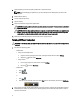
. Close the display and turn the computer upside-down on a flat work surface. NOTE: To avoid damaging the system board, you must remove the main battery before you service the computer. 7. Remove the main battery. 8. Turn the computer top-side up. 9. Open the display. 10. Press the power button to ground the system board. CAUTION: To guard against electrical shock, always unplug your computer from the electrical outlet before opening the display.
After Working Inside Your Computer After you complete any replacement procedure, ensure you connect any external devices, cards, and cables before turning on your computer. CAUTION: To avoid damage to the computer, use only the battery designed for this particular Dell computer. Do not use batteries designed for other Dell computers. 1. Connect any external devices, such as a port replicator, battery slice, or media base, and replace any cards, such as an ExpressCard. 2.
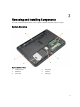
Removing and Installing Components 2 This section provides detailed information on how to remove or install the components from your computer. System Overview Figure 1. Inside View — Back 1. 3. 5. memory modules WLAN card optical drive 2. 4. 6.
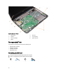
Figure 2. Inside view — Front 1. 3. 5. 7. system board speakers heat sink assembly display 2. 4. 6. I/O board coin-cell battery power connector Recommended Tools The procedures in this document may require the following tools: • Small flat-blade screwdriver • #0 Phillips screwdriver • #1 Phillips screwdriver • Small plastic scribe Removing the SD Card 1. Follow the procedures in Before Working Inside Your Computer. 2. Press in on the SD memory card to release it from the computer.
Installing the SD Card 1. Push the memory card into the compartment until it clicks into place. 2. Follow the procedures in After Working Inside Your Computer. Removing the Battery 1. Follow the procedures in Before Working Inside Your Computer. 2. Slide the release latches outwards to unlock the battery.
3. Lift the battery to remove it from the computer. Installing the Battery 1. Slide the battery into its slot until it clicks into place. 2. Follow the procedures in After Working Inside Your Computer. Removing the Access Panel 1. Follow the procedures in Before Working Inside Your Computer. 2.
3. Remove the screw that secures the access panel. 4. Lift the access panel to remove from the computer.
Installing the Access Panel 1. Slide the access panel into its slot. 2. Tighten the screw to secure the access panel to the computer. 3. Install: a) battery b) SD card 4. Follow the procedures in After Working Inside Your Computer. Removing the Memory Module 1. Follow the procedures in Before Working Inside Your Computer. 2. Remove: a) battery b) SD card c) access panel 3. Pry the securing clips away from the memory module until it pops up.
3. Remove the screw that secures the hard drive and slide the hard drive to disconnect it from the connectors. 4. Lift the tab to remove it from the computer.
Installing the Hard Drive 1. Slide the hard drive in to its slot in the computer. 2. Tighten the screw to secure the hard drive to the computer. 3. Install: a) access panel b) SD card c) battery 4. Follow the procedures in After Working Inside Your Computer. Removing the Optical Drive 1. Follow the procedures in Before Working Inside Your Computer. 2. Remove the battery. 3. Remove the screw that secures the optical drive and slide the optical drive out of the drive bay.
4. Remove the screw that secures the optical-drive bracket to the optical drive and remove it. Installing the Optical Drive 1. Place the optical-drive bracket on to the optical drive. 2. Tighten the screws to secure the optical-drive bracket to the optical drive. 3. Slide the optical drive into the drive bay in the computer. 4. Tighten the screw to secure the optical drive to the computer. 5. Install the battery. 6. Follow the procedures in After Working Inside Your Computer.
3. Remove the screws from the back of the computer. 4. Release the keyboard by pressing the tabs on the palmrest assembly. Slide the keyboard towards the display assembly to access the keyboard cable.
5. Disconnect the keyboard cable from the system board and lift it up to remove it from the computer. Installing the Keyboard 1. Connect the keyboard cable to its connector on the system board. 2. Slide the keyboard in its place on the computer and snap it into place. 3. Flip the computer and tighten the screws to secure the keyboard to the computer. 4. Install the battery. 5. Follow the procedures in After Working Inside Your Computer. Removing the WLAN Card 1.
Installing the WLAN Card 1. Insert the WLAN card into its slot. 2. Press down the WLAN card and tighten the screw to secure the WLAN card to the computer. 3. Connect the antenna cables to their respective connectors marked on the WLAN card. 4. Install: a) access panel b) battery 5. Follow the procedures in After Working Inside Your Computer. Removing the Palmrest 1. Follow the procedures in Before Working Inside Your Computer. 2. Remove: a) b) c) d) 3.
4. Flip the computer and remove the screws that secure the palmrest to the system board. 5. Disconnect the touchpad and power-button cable from the system board.
6. Flip the computer and push the hooks inside the battery bay to release the palmrest. 7. Flip the computer and release the tabs on the sides to lift the palmrest from the computer.
Installing the Palmrest 1. Align and press the palmrest on the computer until it snaps into place on all the sides. 2. Connect the touchpad and power-button cables to the system board. 3. Tighten the screws to secure the palmrest to the system board. 4. Flip the computer and tighten the screws to secure the palmrest to the computer. 5. Install: a) b) c) d) 6. keyboard access panel SD card battery Follow the procedures in After Working Inside Your Computer. Removing the I/O Board 1.
Installing the I/O Board 1. Place the I/O board in its slot. 2. Tighten the screw to secure the I/O board to the computer. 3. Connect the I/O cable to the I/O board. 4. Install: a) b) c) d) e) 5. palmrest keyboard access panel SD card battery Follow the procedures in After Working Inside Your Computer. Removing the Coin-Cell Battery 1. Follow the procedures in Before Working Inside Your Computer. 2. Remove: a) b) c) d) e) 3.
Removing the System Board 1. Follow the procedures in Before Working Inside Your Computer. 2. Remove: a) b) c) d) e) f) g) h) i) j) 3. battery SD card access panel memory module WLAN card hard drive optical drive keyboard palmrest coin-cell battery Peel the tape that secures the display cable to the system board and disconnect the display cable.
4.
5. Remove the screw that secures the system board to the computer and lift the system board from the computer. Installing the System Board 1. Align the system board in its place on the computer. 2. Tighten the screw to secure the system board to the computer. 3. Connect the following cables: a) b) c) d) display DC-In Port speaker I/O board 4. Affix the tape to secure the display cable to the system board. 5. Install: a) b) c) d) e) f) g) h) i) j) 6.
Removing the Heatsink Assembly 1. Follow the procedures in Before Working Inside Your Computer. 2. Remove: a) b) c) d) e) f) g) h) i) j) battery SD card access panel memory module WLAN card hard drive optical drive keyboard palmrest system board 3. Flip the system board and place it on a flat surface. 4. Disconnect fan cable and remove the screws that secure the heatsink assembly to the system board. Lift the heatsink assembly from the system board. Installing the Heatsink Assembly 1.
3. Install: a) b) c) d) e) f) g) h) i) j) 4. system board palmrest keyboard optical drive hard drive memory module WLAN card access panel SD card battery Follow the procedures in After Working Inside Your Computer. Removing the Speakers 1. Follow the procedures in Before Working Inside Your Computer. 2.
3. Unroute the speaker cable from its routing channel and lift the speakers from the computer. Installing the Speakers 1. Place the speakers on to its slot and route the cables through the channels. 2. Install: a) b) c) d) e) f) g) h) i) j) 3. 30 system board palmrest keyboard optical drive hard drive memory module WLAN card access panel SD card battery Follow the procedures in After Working Inside Your Computer.
Removing the Display Assembly 1. Follow the procedures in Before Working Inside Your Computer. 2. Remove: a) b) c) d) e) f) g) h) i) j) 3. battery SD card access panel memory module WLAN card hard drive optical drive keyboard palmrest system board Unroute the display and WLAN antenna cables from their routing channels.
4. Remove the screws that secure the display assembly to the computer. 5. Lift and remove the display assembly from the computer. Installing the Display Assembly 1. Place the display assembly on the computer. 2. Tighten the screws to secure the display assembly. 3. Route the display and WLAN antenna cables to their channels.
4. Install: a) b) c) d) e) f) g) h) i) j) 5. system board palmrest keyboard optical drive hard drive memory module WLAN card access panel SD card battery Follow the procedures in After Working Inside Your Computer. Removing the Display Bezel 1. Follow the procedures in Before Working Inside Your Computer. 2.
3. Press the hinge covers on the side. Lift and remove the hinge covers from the computer. 4. Pry the edges of the display bezel. Remove the display bezel from the computer.
Installing the Display Bezel 1. Align the display bezel in place and snap it in place. 2. Align the hinge covers on display assembly and snap the hinge covers on its place. 3. Install: a) b) c) d) e) f) g) h) i) j) k) 4. display assembly system board palmrest keyboard optical drive hard drive memory module WLAN card access panel SD card battery Follow the procedures in After Working Inside Your Computer. Removing the Display Panel 1. Follow the procedures in Before Working Inside Your Computer.
3. Remove the screws that secure the display panel to the display assembly. Lift the display panel and flip to access the display cable. 4. Peel the tape that secures display cable and disconnect the cable from the connector. Remove the display panel from the display assembly. Installing the Display Panel 1. Connect the display cable to the display panel. 2. Affix the tape to secure the display cable. 3. Place the display panel on the display assembly.
4. Tighten the screws to secure the display panel to the display assembly. 5. Install: a) b) c) d) e) f) g) h) i) j) k) l) m) 6. display hinges display bezel display assembly system board palmrest keyboard optical drive hard drive memory module WLAN card access panel SD card battery Follow the procedures in After Working Inside Your Computer. Removing the Display Hinges 1. Follow the procedures in Before Working Inside Your Computer. 2.
3. Remove the screws that secure the display hinges to the display assembly. Lift the display hinges off the display panel. Installing the Display Hinges 1. Place the display hinges on its place. 2. Tighten the screws to secure the display hinges to the display assembly. 3. Install: a) b) c) d) e) f) g) h) i) j) k) l) 4.
Removing the Camera Module 1. Follow the procedures in Before Working Inside Your Computer. 2. Remove: a) b) c) d) e) f) g) h) i) j) k) l) 3. battery SD card access panel memory module WLAN card hard drive optical drive keyboard palmrest system board display assembly display bezel Disconnect the camera cable from the connector on the camera module.
4. Lift and remove the camera from the display assembly. Installing the Camera Module 1. Connect the camera cable to the connector on the camera module. 2. Align the camera module in its position on the computer. 3. Install: a) b) c) d) e) f) g) h) i) j) k) l) 4. 40 display bezel display assembly system board palmrest keyboard optical drive hard drive memory module WLAN card access panel SD card battery Follow the instructions in After Working Inside Your Computer.
System Setup 3 System Setup enables you to manage your computer hardware and specify BIOS‐level options.
Keys Navigation Allows you to select a value in the selected field (if applicable) or follow the link in the field. Spacebar Expands or collapses a drop‐down list, if applicable. Moves to the next focus area. NOTE: For the standard graphics browser only. Moves to the previous page till you view the main screen. Pressing in the main screen displays a message that prompts you to save any unsaved changes and restarts the system. Displays the System Setup help file.
Option Description L3 Cache Displays the processor L3 cache size. Fixed HDD Displays the model number and capacity of the hard drive. SATA ODD Displays the model number and capacity of the optical drive. AC Adapter Type Displays the type of the AC adapter. System Memory Displays the memory installed on the computer Extended Memory Displays the extended memory installed on the computer. Memory Speed Displays the memory speed.
Option Description External USB Ports Enables or disables external USB ports. The default option is Enabled Microphone Enables or disables microphone. The default option is Enabled USB debug Enables or disables USB debug. The default option is Disabled The Security tab displays the security status and allows you to manage the security features of the computer. Table 4. Security Options Option Description Unlock Setup Status Displays the status of the setup.
Option Description Delete all Security Boot Keys Allows you to delete all security boot keys. Add Boot Option Allows you to add a boot option. Delete Boot Option Allows you to delete a boot option. View Boot Option Priorities Allows you to prioritize the system boot order. Table 6. Exit Option Description Exit Savings Changes Allows you to exit while saving changes. Save Change Without Exit Allows you to save changes without exiting.
System and Setup Password You can create a system password and a setup password to secure your computer. Password Type Description System password Password that you must enter to log on to your system. Setup password Password that you must enter to access and make changes to the BIOS settings of your computer. CAUTION: The password features provide a basic level of security for the data on your computer.
Deleting or Changing an Existing System and/or Setup Password Ensure that the Password Status is Unlocked (in the System Setup) before attempting to delete or change the existing System and/or Setup password. You cannot delete or change an existing System or Setup password, if the Password Status is Locked. To enter the System Setup, press immediately after a power-on or reboot. 1. In the System BIOS or System Setup screen, select System Security and press .
Diagnostics 4 If you experience a problem with your computer, run the ePSA diagnostics before contacting Dell for technical assistance. The purpose of running diagnostics is to test your computer's hardware without requiring additional equipment or risking data loss. If you are unable to fix the problem yourself, service and support personnel can use the diagnostics results to help you solve the problem.
Icon Description Turns on steadily or blinks to indicate battery charge status. Turns on when wireless networking is enabled. Battery Status Lights If the computer is connected to an electrical outlet, the battery light operates as follows: Alternately blinking amber light and white light An unauthenticated or unsupported non-Dell AC adapter is attached to your laptop. Alternately blinking amber light with steady white light Temporary battery failure with AC adapter present.
5 Specifications NOTE: Offerings may vary by region. For more information regarding the configuration of your computer, click Start (Start icon) → Help and Support, and then select the option to view information about your computer. Table 7. System Information Feature Description DRAM bus width 64 bits and 128 bits Flash EPROM 8 MB Table 8.
Feature Description Speakers 2x2W Volume controls program menu and keyboard media-control keys Table 11. Video Feature Description Video type Integrated on system board / discrete Video controller: UMA Intel HD Graphics 4400 (shared memory) Discrete Latitude 3440 NVIDIA GeForce GT740M (2GB DDR3) Latitude 3540 AMD Radeon HD 8850M (2GB DDR5) Data bus: Latitude 3440 64 bits Latitude 3540 128 bits Table 12. Camera Feature Description Camera resolution 0.
Feature Latitude 3540 Description • one USB 2.0 port • • two USB 3.0 ports (rear one with window debug) two USB 2.0 port NOTE: The powered USB 3.0 connector also supports Microsoft Kernel Debugging. The ports are identified in the documentation shipped with your computer. Media card reader one 4-in-1 slot Table 15. Display Feature Latitude 3440 Latitude 3540 Type 14.0 inches HD WLED 15.6 inches HD WLED Height 205.60 mm (8.09 inches) 344.23 mm (13.55 inches) Width 320.90 mm (12.
Table 17. Touchpad Feature Description Active area: 240 dpi X-axis 56.00 mm (2.20 inches) Y-axis 100.00 mm (3.94 inches) Table 18. Battery Feature Description Type • • 4-cell “smart” lithium ion (40 WHr) 6-cell “smart” lithium ion (65 WHr) Height • • 4–cell — 20.00 mm (0.79 inch) 6–cell — 35.40 mm (1.39 inches) Width 46.30 mm (1.82 inches) Depth 272.40 mm (10.72 inches) Weight • • Dimensions: 4–cell — 260 g 6–cell — 360 g Life span 300 discharge/charge cycle Voltage • • 14.
Feature Description Temperature range: Operating 0 °C to 40 °C (32 °F to 104 °F) Non-Operating –40 °C to 70 °C (–40 °F to 158 °F) Table 20. Physical Physical Latitude 3440 Non-Touch Latitude 3540 Touch Non-Touch Touch Height: with 4-cell battery 25.00 mm (0.98 inch) 27.90 mm (1.10 inches) 25.30 mm (1.00 inch) 27.85 mm (1.10 inches) with 6-cell battery 29.60 mm (1.17 inches) 32.90 mm (1.30 inches) 31.30 mm (1.23 inches) 33.85 mm (1.33 inches) Width 346.00 mm (13.62 inches) 376.
Contacting Dell 6 NOTE: If you do not have an active Internet connection, you can find contact information on your purchase invoice, packing slip, bill, or Dell product catalog. Dell provides several online and telephone-based support and service options. Availability varies by country and product, and some services may not be available in your area. To contact Dell for sales, technical support, or customer service issues: 1. Visit dell.com/support 2. Select your support category. 3.