
Owners Manual
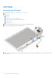
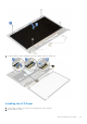
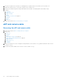
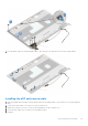
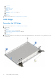
Table Of Contents
- Latitude 3490 Owner’s Manual
- Contents
- Working on your computer
- Disassembly and reassembly
- Recommended tools
- Screw size list
- SIM tray – optional
- SD card
- Base Cover
- Battery
- WLAN Card
- WWAN card – optional
- VGA board
- Memory Module
- Power button board
- Heat sink
- System Fan
- M2. SATA Solid State Drive (SSD)
- Hard drive
- Input-Output board, SD card and coin cell battery holder
- Fingerprint reader – optional
- Coin cell battery
- Speakers
- Touchpad panel
- Display assembly
- System board
- DC-In Port
- Display hinge cover
- LCD Bezel
- Camera
- LCD Panel
- eDP and camera cable
- LCD Hinge
- Palmrest
- Technical specifications
- Processor
- Memory
- Storage specifications
- Audio specifications
- Video specifications
- Webcam specifications
- Wired communications
- Wireless communications
- Ports and Connectors
- Display specifications
- Keyboards Hot Key Definitions
- Touchpad
- Battery specifications
- Adapter options
- System dimensions
- Security options
- Operating conditions
- Technology and components
- System setup options
- BIOS overview
- Entering BIOS setup program
- Navigation keys
- One time boot menu
- System Setup overview
- Accessing System Setup
- General screen options
- System Configuration screen options
- Video screen options
- Security screen options
- Secure Boot screen options
- Intel Software Guard Extensions screen options
- Performance screen options
- Power management screen options
- POST behavior screen options
- Virtualization support screen options
- Wireless screen options
- Maintenance screen options
- System logs screen options
- SupportAssist system resolution
- Verifying system memory in system setup BIOS
- Updating the BIOS
- System and setup password
- Clearing CMOS settings
- Clearing BIOS (System Setup) and System passwords
- Software
- Troubleshooting
- Contacting Dell
3. Place the LCD panel on the LCD back cover and align the LCD panel with the screw holders on the LCD back cover.
4. Replace the 4 M2x2 screws to secure the LCD panel to the LCD back cover.
5. Route the eDP cable through the routing channel and secure the cable to the display panel with an adhesive tape.
6. Install the:
a. LCD bezel
b. display hinge cover
c. display assembly
d. WLAN
e. Installing the WLAN card on page 19
f. hard drive
g. battery
h. base cover
7. Follow the procedure in After working inside your computer
eDP and camera cable
Removing the eDP and camera cable
1. Follow the procedure in Before working inside your computer.
2. Remove the:
a. base cover
b. hard drive
c. battery
d. Removing the WLAN card on page 18
e. Removing the WWAN daughterboard on page 19
f. display assembly
g. display hinge cover
h. LCD bezel
i. LCD panel
3. Remove the 5 M2.5x2.5 screws securing the left hinge bracket to the LCD back cover [1] and lift the bracket away from the
LCD back cover [2].
4. Disconnect the camera cable from its connector on the LCD back cover [3].
54
Disassembly and reassembly