Latitude 5289 2-in-1 Owner's Manual Regulatory Model: P29S Regulatory Type: P29S001
Notes, cautions, and warnings NOTE: A NOTE indicates important information that helps you make better use of your product. CAUTION: A CAUTION indicates either potential damage to hardware or loss of data and tells you how to avoid the problem. WARNING: A WARNING indicates a potential for property damage, personal injury, or death. © 2017 Dell Inc. or its subsidiaries. All rights reserved. Dell, EMC, and other trademarks are trademarks of Dell Inc. or its subsidiaries.
Contents 1 Working on your computer............................................................................................................................. 7 Safety instructions............................................................................................................................................................. 7 Before working inside your computer..............................................................................................................................
Removing the smart card cage................................................................................................................................ 22 Installing the smart card cage.................................................................................................................................. 23 Heat Sink...........................................................................................................................................................................
Changing the screen resolution................................................................................................................................47 Connecting to external display devices................................................................................................................... 48 Camera features...............................................................................................................................................................
Security screen options...................................................................................................................................................66 Secure Boot screen options........................................................................................................................................... 68 Intel software guard extensions screen options...........................................................................................................
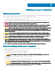
1 Working on your computer Safety instructions Use the following safety guidelines to protect your computer from potential damage and to ensure your personal safety. Unless otherwise noted, each procedure included in this document assumes that the following conditions exist: • You have read the safety information that shipped with your computer. • A component can be replaced or, if purchased separately, installed by performing the removal procedure in reverse order.
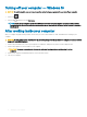
Turning off your computer — Windows 10 CAUTION: To avoid losing data, save and close all open files and exit all open programs before you turn off your computer. 1 Click or tap 2 Click or tap . and then click or tap Shut down. NOTE: Ensure that the computer and all attached devices are turned off. If your computer and attached devices did not automatically turn off when you shut down your operating system, press and hold the power button for about 6 seconds to turn them off.
2 Removing and installing components This section provides detailed information on how to remove or install the components from your computer. Screw size list Table 1. Latitude 5289 - Screw size list Component Back cover M2.5 x 5 M2.0 x 2 M2.0 x 3 M2.0 x 4L M 2.0 x 1.7 M 2 2.0 x 2.
Removing the Micro Secure Digital (SD) Card 1 Follow the procedure in Before working inside your computer. 2 Press in on the Micro SD card to release it from the computer. 3 Slide the Micro SD card out of the computer. Installing the Micro Secure Digital (SD) Card 1 Slide the Micro SD into the slot until it clicks into place. 2 Follow the procedures in After working inside your computer.
3 Use a plastic scribe to pry the base cover starting from the hinges at the top edge of the base cover and lift it from the computer. NOTE: The recesses are located near the hinges at the rear side of the computer. Installing the base cover 1 Align the base cover tabs to the slots on the edges of the computer. 2 Press the edges of the cover until it clicks into place. 3 Tighten the M2.5 x 5.0 captive screws to secure the base cover to the computer.
Battery Lithium-ion battery precautions CAUTION: • Exercise caution when handling Lithium-ion batteries. • Discharge the battery as much as possible before removing it from the system. This can be done by disconnecting the AC adapter from the system to allow the battery to drain. • Do not crush, drop, mutilate, or penetrate the battery with foreign objects. • Do not expose the battery to high temperatures, or disassemble battery packs and cells.
Installing battery 1 Insert the battery into the slot on the computer. 2 Connect the battery cable to the connector on the system board. 3 Replace the M 2 x 4L screws to secure the battery to the computer. 4 Install the: a b 5 base cover SD card Follow the procedure in After working inside your computer. PCIe Solid State Drive (SSD) Removing the NVMe SSD card 1 Follow the procedure in Before working inside your computer.
Installing the NVMe SSD 1 Insert the NVMe SSD card into the connector. 2 Install the thermal bracket over the SSD card. 3 Replace the M2.0 x 3.0 screws to secure the SSD thermal bracket. 4 Install the: 5 a battery b c NOTE: If you have not removed the battery, you must connect the battery cable to the system board. base cover MicroSD card Follow the procedure in After working inside your computer. WLAN card Removing the WLAN card 1 Follow the procedure in Before working inside your computer.
c d Disconnect the WLAN cables from the connectors on the WLAN card [3]. Remove the WLAN card from the computer [4]. Installing the WLAN card 1 Insert the WLAN card into the connector on the system board. 2 Connect the WLAN cables to the connectors on the WLAN card. 3 Place the metal bracket and replace the M2.0 x 3.0 screw to secure WLAN card to the computer. 4 Install the: 5 a battery b c NOTE: If you have not removed the battery then you must connect the battery cable to the system board.
a b c d Remove the M2.0 x 3.0 screw that secures the metal bracket to the WWAN card . Lift the metal bracket that secures the WWAN card . Disconnect the WWAN cables from the connectors on the WWAN card Lift the WWAN card from the computer. Installing the WWAN card 1 Insert the WWAN card into the connector on the system board. 2 Connect the WWAN cables to the connectors on the WWAN card. 3 Place the metal bracket and replace the M2.0 x 3.0 screw to secure the WLAN card to the computer.
Installing the power board 1 Insert the power board into the slot. 2 Replace the M2.0x3.0 screws to secure the power board to the computer. 3 Connect the power board cable to the connector on the system board. 4 Affix the coin cell battery in the slot on the computer. 5 Install the: a b c 6 battery base cover MicroSD card Follow the procedure in After working inside your computer. Speaker Removing the speaker module 1 Follow the procedure in Before working inside your computer.
4 To release the speaker module: a b 5 Disconnect the speaker cable from the connector on the system board [1]. Un route the speaker cable by removing the tapes that secure the cable [2]. To remove the speaker module: a b 18 Un route the speaker cable from the routing clips near the palm rest [1]. Lift the speaker module from the computer.
NOTE: You can use a plastic scribe to lift the speaker module from the computer. Installing the speaker module 1 Place the speaker module into the slots on the computer. 2 Route the speaker cable through the routing channel and secure it with tapes. 3 Connect the speaker cable to the connector on the system board. 4 Connect the LED cable to the connector on the palm rest. 5 Install the: a b c d 6 power board battery base cover Micro SD Follow the procedure in After working inside your computer.
b c d e Disconnect the finger print reader cable from the fingerprint reader board and the USH board [2]. Remove the M2 x 3 screw that secures the fingerprint reader bracket [3]. Lift the fingerprint reader bracket from the fingerprint reader board [3]. Lift the fingerprint reader board from the slot on the computer. NOTE: Fingerprint reader board is affixed and you may need a plastic scribe to lift the fingerprint reader board.
a b c 3 Micro SD base cover battery To remove the LED board: a b c d Disconnect the LED board cable from the LED board [1]. Remove the tape that secures the LED board to the touchpad panel [2]. Remove the M2 x 3 screws that secure the LED board [3]. Lift the LED board from the computer [4]. Installing the LED board 1 Install the LED board into the slot. 2 Replace the M2 x 3 screws to secure the LED board. 3 Affix the tape to secure the LED board. 4 Connect the LED board cable to the LED board.
Removing the smart card cage NOTE: Always remove the smart card from the smart card reader. 1 Follow the procedure in Before working inside your computer. 2 Remove: a b c d 3 Micro SD base cover battery SSD card To disconnect the cables: a b c Disconnect the smart card cable [1] and fold it away from the smart card cage. Disconnect the LED board cable [2] and fold it away from the smart card cage. Peel the SSD thermal pad from the SSD slot 3].
Installing the smart card cage 1 Slide the smart card cage into the slot to align with the screw holders on the computer. 2 Replace the M2.0 x 1.7 screws to secure the smart card cage to the computer. 3 Affix the thermal pad in the SSD slot. 4 Affix the LED board cable and connect it to the LED board on the computer. 5 Affix the smart card cable and connect it to the USH board on the computer .
b c d Remove the M2.0 x 3.0 screws that secure the fan to the system board. Remove the M2.0 x 3.0 screws that secure the heat sink to the system board [2]. Lift the heat sink assembly from the system board. Installing heat sink assembly 1 Align the heat sink assembly with screw holders on the system board. 2 Replace the M2.0 x 3.0 screws to secure the heat sink to the system board.
d e WLAN card WWAN card 3 Peel the tapes that secure the antenna cables and un route the cables from the routing clips. 4 Disconnect the : a IR camera and touchscreen cable [1]. b Remove the M 2 x 1.7L screws that secure the eDP bracket and lift it away from the computer [2]. c Disconnect the eDP cable from the system board [3]. d Disconnect th G-sensor and eDP cables [4].
5 Lift the base of the computer away from the display assembly. 6 To remove the display assembly: 26 a Place the base of the computer with the display assembly at 270 degrees (laptop) or 90 degrees (tablet). b c NOTE: If the system is used as a laptop, then display assembly should be at 270 degrees and for a fully closed tablet configuration, the display should be at 90 degrees. Remove the M2.5 x 4.0 screws that secure the display hinge brackets [1].
Installing the display assembly 1 Place the base of the computer on a flat surface. 2 Install the display assembly by aligning it with the display hinge screw holders. 3 Replace the M2.5 x 4.0 screws to secure the display assembly. 4 Close the display assembly and flip the computer. 5 Connect the cables: a b c G-sensor and eDP cable Place the eDP bracket on the eDP cable and replace the M 2 x 1.7L on the bracket.
2 Slide the dummy SIM card tray out of the system. System Board Removing system board 1 Follow the procedure in Before working inside your computer. 2 Remove the: 3 a b Micro SD SIM card tray c d e f g h i If your system is shipped with a WWAN card, it will have a dummy SIM card tray. Dummy SIM tray base cover battery SSD card WLAN card WWAN card Heatsink assembly Disconnect the following cables from the system board .
4 Disconnect the eDP cable: NOTE: To disconnect the eDP cable, remove the M 2 x 1.7L screws that secure the eDP bracket and lift it away from the computer, Disconnect the eDP cable from the system board. 5 To release the cables: a Flip the coin cell battery to reveal the speaker cable [1]. b Disconnect the speaker cable from the system board [2]. c Disconnect the power board cable from the system board [3].
6 Peel the tapes that secure antenna cables and un route the cables from the routing clips. 7 To remove the system board: a b c d 30 Remove the M2.0 x 4L screws on the USB Type-C bracket [1]. Lift the USB Type-C bracket from the Type-C module [2]. Remove the M2.0 x 3.0 screws that secure the system board to the computer [3]. Lift the system board away from the computer[4].
Installing system board 1 Align the system board with the screw holders on the computer. 2 Replace the M2.0 x 3.0 screws to secure the system board to the computer. 3 Place the USB Type-C bracket on the Type-C module. 4 Replace the M 2.0 x 4L screws to secure the USB Type-C bracket to the Type-C module. 5 Route the antenna cable through the routing clips and affix the tapes to secure the antenna cables. 6 Connect the power board and the speaker cable to the system board.
Removing the real time clock (RTC) 1 Follow the procedure in Before working inside your computer. 2 Remove the: a b mircro SD card SIM card tray c d e f g h i NOTE: SIM Card tray is available only if your computer is shipped with a WWAN card. base cover battery SSD card WLAN card WWAN card heat sink assembly system board NOTE: RTC is located on the system board and hence system board removal is a requirement. 3 Disconnect the RTC cable to release it from the system board.
3 Follow the procedure in After working inside your computer. RTC is located on the system board and hence system board must be installed after the installation of the RTC. Keyboard Removing keyboard assembly NOTE: The keyboard and the keyboard tray together are called the keyboard assembly. 1 Follow the procedure in Before working inside your computer. 2 Remove the: 3 a b Micro SD SIM card tray c d e f g h i NOTE: SIM Card tray is available only if your computer is shipped with a WWAN card.
b Lift the keyboard from the chassis [2]. Removing keyboard from the keyboard tray 1 Follow the procedure in Before working inside your computer. 2 Remove the keyboard 3 Remove the keyboard from the keyboard support tray: a b 34 Remove the M2.0 x 2.0 screws that secure the keyboard to the keyboard assembly [1]. Lift the keyboard away from the keyboard support tray [2].
Installing keyboard to the keyboard tray 1 Align the keyboard with the screw holders on the keyboard tray. 2 Tighten the M2.0 x 2.0 screws to secure the keyboard to the keyboard tray. 3 Install the keyboard. Installing keyboard assembly NOTE: The keyboard and the keyboard tray together are called the keyboard assembly. 1 Align the keyboard assembly with the screw holders on the chassis. 2 Replace the M2.0 x 3.0 screws that secure the keyboard to the chassis.
Display Panel Removing the display panel 1 Follow the procedure in Before working inside your computer. 2 Remove the: a b c d e f 3 To release the display panel: a b c 4 Micro SD base cover battery WLAN card WWAN card display assembly Pry the display panel from the display hinges [1]. Push the display hinges from the recesses at the bottom edge [2]. Work your way around the edges to release the display panel [3,4]. Flip the display panel.
5 Disconnect the cables: a b c d G-sensor cable [1]. Peel the tape that secures the display cable [2]. Lift the metal tab that secures the display cable [3]. Disconnect the display cable from the display panel.
Installing the display panel 1 Place the display panel near the left over portion of the display cover . 2 Connect the display cable from the display cover to the display panel. 3 Affix the tape to secure the display cable on the display panel. 4 Connect the G-sensor cable to the connector on the display panel. 5 Flip the display panel on the display cover. 6 Press the edges to secure the display panel to the display assembly.
Installing the G-sensor board 1 Place the G-sensor board on the display cover. 2 Connect the display cable to the G-sensor board. 3 Flip the G-sensor board to align with the screw holder on the display cover. 4 Replace the M2.0 x 3.0 screw to secure the G-sensor board to the display cover. 5 Install the: a b c d e f 6 Idisplay panel WLAN card WWAN card battery base cover Micro SD Follow the procedure in After working inside your computer.
e f g 3 WWAN card display assembly display panel To remove the camera: a b Disconnect the camera cable from the camera module [1]. Peel the camera module to lift it away from the display cover [2]. Installing the camera 1 Insert the camera module in the slot on the display cover. 2 Affix the camera module to secure the module to the display cover. 3 Connect the camera cable to the connector on the camera module.
Replacing palm rest 1 Follow the procedure in Before working inside your computer. 2 Remove the: a b c d e f g h i j k l m n base cover battery SSD module WLAN card WWAN card power board heat sink assembly RTC LED board speaker smart card cage display assembly system board keyboard The component you are left with is the palmrest. 3 Replace the palmrest.
h i j k l m n 5 heat sink power board WLAN card WWAN card PCIe SSD battery base cover Follow the procedure in After working inside your computer.
3 Technology and components This chapter details the technology and components available in the system. Topics: • Power adapter • Processors • Chipset • Memory features • Display • Camera features • Hard drive • USB features • HDMI 1.4 Power adapter This laptop is shipped with 45W or 65W power adapters. WARNING: When you disconnect the power adapter cable from the laptop, grasp the connector, not the cable itself, and then pull firmly but gently to avoid damaging the cable.
Figure 1. Processor Verifying processor usage in task manager 1 Right click on the taskbar. Select Task Manager 2 You can also access the task manager by clicking CTRL+ALT+DEL keys. The Windows Task Manager window is displayed. 3 Click the Performance tab in the Windows Task Manager window. Verifying processor usage in resource monitor 1 Right click the on tablet. 2 Select Start Task Manager. The Windows Task Manager window is displayed.
3 Click the Performance tab in the Windows Task Manager window. The processor performance details are displayed. 4 Click Open Resource Monitor. Chipset The chipset is integrated on the processor. Identifying chipset in device manager on Windows 10 NOTE: The Chipset information displayed is a generic image and may be different from what is displayed. 1 Type Device Manager in the Ask me anything field. Device Manager window appears. 2 Expand System Devices and search for the chipset.
Memory features Memory is integrated on the system board and it cannot be replaced as a module. Latitude 5289 supports the following memory configurations: • 16 G 1866 MHz LPDDR3 • 4 G 1866 MHz LPDDR3 • 8 G 1866 MHz LPDDR3 Verifying system memory in setup 1 Turn on or restart your notebook. 2 When the Dell logo appears, press F2. Entering BIOS setup message appears. 3 On the left pane, select Settings > General > System Information, The memory information is displayed on the right pane.
Testing memory using ePSA 1 Turn on or restart your computer. 2 Press F12 or press Fn+PWR to invoke the ePSA diagnostics. The PreBoot System Assessment (PSA) starts on your computer. NOTE: If you wait too long and the operating system logo appears, continue to wait until you see the login screen/desktop screen. Turn off the computer and try again. If the memory test results in 25 or less errors, or then the RMT basic feature automatically fixes the issues.
Connecting to external display devices Follow these steps to connect your computer to an external display device: 1 Ensure that the projector is turned on and plug the projector cable into a video port on your computer. 2 Press the Windows logo+P key. 3 Select one of the following modes: • PC screen only • Duplicate • Extend • Second Screen only NOTE: For more information, see the document that is shipped with your display device.
Starting the camera application 1 Tap or click the Windows button and select All apps. 2 Select Camera from the apps list. 3 If the Camera App is not available in the apps list, search for it.
Hard drive This section explains how to identify the hard drive type installed in the system. Storage options This laptop supports M.2 SATA SSD and M.2 PCIe NVMe SSDs. Identifying the storage device in the BIOS 1 Turn on or restart your laptop. 2 When the Dell logo appears, perform one of the following actions to enter the BIOS setup program: • Tap F2 until the Entering BIOS setup message appears. To enter the Boot selection menu, tap F12.
finally has the answer to the consumers' demands with a theoretically 10 times faster than its predecessor. In a nutshell, USB 3.1 Gen 1 features are as follows: • Higher transfer rates (up to 5 Gbps) • Increased maximum bus power and increased device current draw to better accommodate power-hungry devices • New power management features • Full-duplex data transfers and support for new transfer types • Backward USB 2.
Applications USB 3.0/USB 3.1 Gen 1 opens up the laneways and provides more headroom for devices to deliver a better overall experience. Where USB video was barely tolerable previously (both from a maximum resolution, latency, and video compression perspective), it's easy to imagine that with 5-10 times the bandwidth available, USB video solutions should work that much better. Single-link DVI requires almost 2Gbps throughput. Where 480Mbps was limiting, 5Gbps is more than promising. With its promised 4.
HDMI 1.
4 System specifications NOTE: Offerings may vary by region. The following specifications are only those required by law to ship with your computer. For more information about the configuration of your computer, go to Help and Support in your Windows operating system and select the option to view information about your computer.
Feature Specification • 7th generation Intel Core i7-7600U Processor (up to 3.9GHz, 4M cache, 15W), vPro Memory specifications Feature Specification Memory capacity up to 16 GB (on board) Memory type LPDDR3 SDRAM—1866 MHz Video specifications Feature Specification Type Integrated on system board Unified Memory Architecture controller Intel HD Graphics 620 External display support • On system – eDP (internal display), HDMI 1.
Feature Specification Speakers Two Internal speaker amplifier 2 W (RMS) per channel Volume controls Volume control buttons and Hot keys Storage options Feature Storage options Specification • M.2 128 GB/256 GB/360 GB SATA SSD • M.2 256 GB/512 GB/1 TB PCIe NVMe SSD • M.2 256 GB/512 GB PCIe NVMe SED • M.
Ports and connector specifications Feature Audio Video USB Specification • Universal audio jack • Volume buttons HDMI 1.4 • One USB 3.1 Gen 1 • One USB 3.1 Gen 1 with PowerShare • Two USB 3.1 Gen 1 with Type-C Memory card reader Micro SD 4.0 Universal Subscriber One Identity Module (uSIM) card-WWAN Docking port USB Type-C docking Express Card None Touchpad specifications Feature Active area Multi-touch Specification • X-axis - 90.5 mm (3.56 inches) • Y-axis - 50.0 mm (1.
Display specifications Feature Specification Type 12.5–inch Touch with corning gorilla glass 4, active pen support, anti-reflective and anti-smudge Luminance 255 nits (typical) Diagonal 317.5 mm (12.5 inches) Native resolution 1920x1080 Refresh rate 60 Hz Maximum viewing angles—horizontal 80/-80 degrees Maximum viewing angles—vertical 80/-80 degrees Pixel pitch FHD 0.
Feature Dimensions—45 W Dimensions—65 W Dimensions—90W Specification • 90 W—0.291 kg (0.641 lb) • Height—22 mm (0.87 inch) • Width—55 mm (2.17 inches) • Depth—87 mm (3.42 inches) • Height—99 mm (3.90 inches) • Width—66 mm (2.60 inches) • Depth—22 mm (0.87 inch) • Height-130 mm (5.12 inches) • Width-66 mm (2.60 inches) • Depth-22 mm (0.
Feature Specification Voltage 7.6 VDC Life span 300 discharge per charge cycles 60 WHr Long Life Cycle Polymer Battery: Length 238 mm (9.37 inches) Width 95.9 mm (3.78 inch) Height 5.7 mm (0.22 inch) Weight 270 g (0.6 lb) Voltage 7.
Altitude— maximum Specifications Operating 0 m to 3048 m (0 to 10,000 ft) 0° to 40°C (32° to 104°F) Non-operating 0 m to 10668 m (0 to 35,000 ft) Airborne contaminant level G2 or lower as defined by ISA S71.
5 System setup System setup enables you to manage your notebook hardware and specify BIOS level options.
– Windows Boot Manager • Other Options: – BIOS Setup – BIOS Flash Update – Diagnostics – Change Boot Mode Settings Navigation keys NOTE: For most of the System Setup options, changes that you make are recorded but do not take effect until you restart the system. Keys Navigation Up arrow Moves to the previous field. Down arrow Moves to the next field. Enter Selects a value in the selected field (if applicable) or follow the link in the field.
Option Description Boot sequence options Boot list options • CD/DVD/CD-RW Drive • Onboard NIC • Windows boot manager • WindowsIns • Legacy • UEFI—selected by default Advanced Boot Options This option allows you the legacy option ROMs to load. By default, the Enable Legacy Option ROMs is disabled. Enable Attempt Legacy Boot is disabled by default. UEFI boot path security • Always, except internal HDD • Always • Never Date/Time Allows you to change the date and time.
Option Description • Enable the Thunderbolt ports • Always Allow dell docks—enabled by default • Enable External USB Port—enabled by default • Enable Thunderbolt Boot Support • Enable Thunderbolt (and PCIE behind TBT) Preboot • Security level-No security • Security level-User configuration • Security level-Secure connect • Security level- Display port only NOTE: USB keyboard and mouse always work in the BIOS setup irrespective of these settings.
Option Description • Never Keyboard Backlight with AC The Keyboard Backlight with AC option does not affect the main keyboard illumination feature. Keyboard Illumination will continue to support the various illumination levels. This field has an effect when the backlight is enabled. This option is enabled by default. Keyboard Backlight Timeout on AC The Keyboard Backlight Timeout dims out with AC option. The main keyboard illumination feature is not affected.
Option Description NOTE: Successful password changes take effect immediately. Default setting: Not set Strong Password Allows you to enforce the option to always set strong passwords. Default Setting: Enable Strong Password is not selected. NOTE: If Strong Password is enabled, the Admin and System passwords must contain at least one uppercase character, one lowercase character and be at least 8 characters long.
Option Description NOTE: The Activate and Disable options will permanently activate or disable the feature and no further changes are allowed CPU XD Support Allows you to enable the Execute Disable mode of the processor. Enable CPU XD Support—enabled by default OROM Keyboard Access Allows you to set an option to enter the Option ROM Configuration screens using hotkeys during boot.
Performance screen options Option Description Multi-Core Support This field specifies whether the process has one or all cores enabled. The performance of some applications improves with the additional cores. This option is enabled by default. Allows you to enable or disable multi-core support for the processor. The installed processor supports two cores. If you enable Multi-Core Support, two cores are enabled. If you disable Multi-Core Support, one core is enabled.
Option Description NOTE: This feature is only functional when the AC power adapter is connected. If the AC power adapter is removed during Standby, the system setup removes power from all the USB ports to conserve battery power. • Enable USB Wake Support • Wake on Dell USB-C dock Default setting: The option is disabled. Wireless Radio Control Allows you to enable or disable the feature that automatically switches from wired or wireless networks without depending on the physical connection.
Option Description NOTE: All charging mode may not be available for all the batteries. To enable this option, disable the Advanced Battery Charge Configuration option. Sleep mode • OS Automatic selection—enabled by default Force S3 Type-C connector power • 7.5 Watts • 15 Watts—enabled by default POST behavior screen options Option Description Adapter Warnings Allows you to enable or disable the system setup (BIOS) warning messages when you use certain power adapters.
Option Description • Extended BIOS POST Time Security audit Full Screen Log Warnings and errors Auto Allows you to create an extra preboot delay. The options are: • 0 seconds—enabled by default.
Wireless screen options Option Description Wireless Switch Allows to set the wireless devices that can be controlled by the wireless switch. The options are: • WWAN • GPS (on WWAN Module) • WLAN/WiGig • Bluetooth All the options are enabled by default. NOTE: For WLAN and WiGig enable or disable controls are tied together and they cannot be enabled or disabled independently. Wireless Device Enable Allows you to enable or disable the internal wireless devices.
System logs screen options Option Description BIOS Events Allows you to view and clear the System Setup (BIOS) POST events. Thermal Events Allows you to view and clear the System Setup (Thermal) events. Power Events Allows you to view and clear the System Setup (Power) events. Updating the BIOS in Windows It is recommended to update your BIOS (System Setup), on replacing the system board or if an update is available.
Assigning a system password and setup password You can assign a new System Password only when the status is in Not Set. To enter the system setup, press F2 immediately after a power-on or re-boot. 1 In the System BIOS or System Setup screen, select Security and press Enter. The Security screen is displayed. 2 Select System Password and create a password in the Enter the new password field. Use the following guidelines to assign the system password: • A password can have up to 32 characters.
6 Troubleshooting Enhanced Pre-Boot System Assessment (ePSA) diagnostics The ePSA diagnostics (also known as system diagnostics) performs a complete check of your hardware. The ePSA is embedded with the BIOS and is launched by the BIOS internally.
The system will not shutdown when displaying the Diagnostic Error Codes. Diagnostic Error Codes will always supersede any other use of the LED. For instance, on Notebooks, battery codes for Low Battery or Battery Failure situations will not be displayed when Diagnostic Error Codes are being displayed: Table 3.
7 Contacting Dell NOTE: If you do not have an active Internet connection, you can find contact information on your purchase invoice, packing slip, bill, or Dell product catalog. Dell provides several online and telephone-based support and service options. Availability varies by country and product, and some services may not be available in your area. To contact Dell for sales, technical support, or customer service issues: 1 Go to Dell.com/support. 2 Select your support category.