Latitude 12 Rugged Extreme Tablet – 7212 Owner's Manual Regulatory Model: T03H Regulatory Type: T03H002 January 2021 Rev.
Notes, cautions, and warnings NOTE: A NOTE indicates important information that helps you make better use of your product. CAUTION: A CAUTION indicates either potential damage to hardware or loss of data and tells you how to avoid the problem. WARNING: A WARNING indicates a potential for property damage, personal injury, or death. © 2018 2021 Dell Inc. or its subsidiaries. All rights reserved. Dell, EMC, and other trademarks are trademarks of Dell Inc. or its subsidiaries.
Contents Chapter 1: Working on your computer........................................................................................... 6 Safety instructions.............................................................................................................................................................. 6 Before working inside your computer.............................................................................................................................
Heat sink for SSD.............................................................................................................................................................. 34 Removing heatsink for SSD or PCIE.......................................................................................................................34 Installing heatsink for SSD or PCIE.........................................................................................................................
Video specifications.......................................................................................................................................................... 62 Camera specifications...................................................................................................................................................... 62 Communication specifications...................................................................................................................................
1 Working on your computer Topics: • • • • Safety instructions Before working inside your computer Turning off your computertablet — Windows 10 After working inside your computer Safety instructions Use the following safety guidelines to protect your computer from potential damage and to ensure your personal safety. Unless otherwise noted, each procedure included in this document assumes that the following conditions exist: ● You have read the safety information that shipped with your computer.
CAUTION: To disconnect a network cable, first unplug the cable from your computer and then unplug the cable from the network device. 5. Disconnect all network cables from the computer. 6. Disconnect your computer and all attached devices from their electrical outlets. 7. Turn the computer upside-down on a flat work surface. NOTE: Ensure to close the display if the system is a laptop. To avoid damaging the system board, remove the main battery before you service the computer. 8. Remove the main battery. 9.
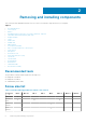
2 Removing and installing components This section provides detailed information on how to remove or install the components from your computer.
Table 1. Latitude 7212 Rugged Extreme Tablet screw size list (continued) Componen t M2*2 M2*2.5 M2*3 M2*4 M2*5 M2.5*3 M2.5*5 M2.5*8 Protective Rubber Bumper( all four corners) 8 WLAN 1 WWAN 1 M.2 SSD 1 System Board Assembly (System Board and Fan) Power Button Assembly 14 1 DC-In Cable and Bracket Kensington Lock Bracket 3 3 LCD Bezel Bracket Docking 19 1 Battery Removing the battery WARNING: Using an incompatible battery may increase the risk of fire or explosion.
The battery is released from the battery bay. 4. Lift the edge of the battery that pops up.
Removing and installing components 11
Removing the battery when the cross strap is attached - Optional WARNING: Using an incompatible battery may increase the risk of fire or explosion. Replace the battery only with a compatible battery purchased from Dell. The battery is designed to work with your Dell Tablet. Do not use a battery from any other computer with your tablet.
The battery is released from the battery bay. 5. Lift the edge of the battery that pops up to release the battery. Installing the battery 1. Insert the battery into the battery slot. NOTE: Ensure the metal pin of the battery is aligned in place. 2. Slide the battery into the slot until it clicks into place. 3. Make sure the battery latch is back to the locked state. NOTE: There are two battery. Perform steps 1 to 3 to install battery 1 and battery 2 on the tablet. 4.
Installing the battery when the cross strap is attached - Optional 1. Insert the battery into the battery slot. 2. Slide the battery into the slot until it clicks into place and locked. 3. Slide the velcro strap into the strap holder. 4. Affix the velcro strap. 5. Follow the procedure in After working inside your computer. Subscriber Identification Module (SIM) card Removing uSIM 1. Follow the procedure in Before working inside your computer. 2. Remove the left battery. 3.
Inserting the uSIM 1. Remove the leftbattery 2. To insert the uSIM: a. Lift the latch and remove the SIM slot cap. b. Insert the SIM in the slot until it is locked. NOTE: Ensure the gold chip is facing down in the slot. c. Press the SIM slot cap to initial state. 3. Follow the procedure in After working inside your computer. Display assembly Removing display assembly 1. Follow the procedure in Before working inside your computer. 2. Remove the: a. Battery 3.
5. Insert a plastic scribe near the Windows button [1]. NOTE: Pointed tip of the plastic scribe should be inserted to avoid damage to the seal on the LCD and to the clips that secure the LCD display to the tablet chassis. 6. Pry the edges starting from Windows button clockwise [1,2]. NOTE: Gently pry the edges evenly to unlock the plastic clips that secures the display assembly to the tablet chassis. 7. Lift the display assembly [1] by angle 15° and slide it from the chassis [2].
8. Flip the display assembly by an angle less than 90°. NOTE: Ensure not to flip more than 90° angle, as the display assembly ports and cables are connected to the system board and may damage the display cables. 9. Before removing display assembly: a. Place the bottom edge of the display panel inside the bottom edge of the rear chassis. b. Flip open the display panel to 90° angle and lay it angled on the tablet chassis. 10.
a. Remove the adhesive tape that secures the LVDS cable on the system board [1]. b. Lift the latch with a plastic scribe on the system board. c. Disconnect the connector of LVDS cable from the slot by a plastic scribe [2] and remove the cable [3]. d. Remove the adhesive tape that secures the Function Key cable on the system board [4]. e. Lift the latch by a plastic scribe and release the Touch cable connected to the system board [5]. NOTE: Disconnect only the display cable from the system board.
NOTE: DO NOT remove any cable or adhesive tape from the display panel, unless you are replacing the cables separately. Installing display assembly 1. Place the system chassis on a plane surface. 2. Place the bottom edge of the display assembly inside the bottom edge of the rear chassis. 3. Rest the display assembly by less than 90° angle. NOTE: Use a support to attain the required angle. 4. Connect the touch cable, function keys cable, and LVDS cable to the connector on the system board. 5.
NOTE: DO NOT tighten the screws too much, to avoid damage the screws thread. 10. Install the: a. Battery 11. Follow the procedure in After working inside your computer. Stylus Removing stylus 1. Follow the procedure in Before working inside your computer. 2. Locate the stylus at the top of the tablet. 3. Pull the stylus by the thread upward. NOTE: Avoid pulling the stylus attached with the stretchable thread. 4. Pull the stylus from the groove on the tablet.
NOTE: Avoid hanging the stylus detached from its groove when not in use. 3. Follow the procedure in After working inside your computer. WLAN card Removing WLAN card 1. Follow the procedure in Before working inside your computer. 2. Remove the: a. Battery b. Display assembly 3. To remove the WLAN card: a. b. c. d. e. Place the back side of system on a flat surface. Locate the WLAN card. Remove the screw that secures the WLAN bracket to the system board [1]. Lift the metal bracket [2] from the WLAN card.
Installing WLAN card 1. Insert the WLAN card in the slot on the system board. NOTE: Ensure that the metal pin is downwards towards the slot on the system board, and an angle LESS than 30° is maintained. 2. Connect the WLAN cables to the connectors on the WLAN card. NOTE: Ensure that cables are aligned straight and gently press on the top to fit the cable copper head on WLAN card button pin. 3. To secure the WLAN card, place the antenna bracket and tighten the M2.0 x 3.0 screw. 4. Install the: a.
Installing WWAN card 1. Insert the WWAN card in the slot on the system board. NOTE: Ensure that the metal pin is downwards towards the slot on the system board. 2. Connect the WWAN cables to the connectors on the WWAN card. NOTE: The IMEI number is visible on the WWAN card. 3. To secure the WWAN card, place the metal bracket and tighten the M2.0 x 3.0 screw. 4. Install the: a. Display assembly b. Battery 5. Follow the procedure in After working inside your computer. CMOS battery Removing CMOS battery 1.
b. Locate the CMOS battery. c. Lift the fingerprint reader cable latch by a plastic scribe and push the cable gently from the latch [1]. NOTE: Ensure to unlock the fingerprint reader cable to release the CMOS battery. d. Remove the CMOS cable from the routing clip on the system board [2]. e. Push the pin connected to the system board CMOS slot by a plastic scribe [3]. NOTE: Push the cable pin head with a plastic scribe at an angle not more than 30°. DO NOT push too hard, as it may damage the cable pin head.
a. Display assembly b. Battery 6. Follow the procedure in After working inside your computer. Power button assembly Removing power button assembly 1. Follow the procedure in Before working inside your computer. 2. Remove the: a. Battery b. Display assembly 3. To remove the power button assembly: a. b. c. d. Place the back side of system on a flat surface. Locate the power button assembly. Lift the latch by an angle 35° to unlock and gently release the power button assembly cable [1].
NOTE: Power button assembly bus cable is routed between the square gap in the power button bracket. f. Release the adhesive tape that secures the power button assembly. g. Push and release the power button assembly from the chassis by a plastic scribe [4]. h. Lift and remove the power button bracket together with the power button assembly. NOTE: Power button is encapsulated within a power button bracket. Installing power button assembly 1. Assemble the power assembly button with the power button bracket.
6. Install the: a. Display assembly b. Battery 7. Follow the procedure in After working inside your computer. Micro serial port and power connector port Removing micro serial port and power connector port 1. Follow the procedure in Before working inside your computer. 2. Remove the: a. Battery b. Display assembly 3. To remove the micro serial port and power connector port: a. Place the back side of system on a flat surface. b. Locate the micro serial port and power connector port. c.
Power connector port and micro serial port are assembled as one single component to connect on the tablet system board. NOTE: Malfunction of either component requires to remove both power connector port and micro serial port.
Installing micro serial port and power connector port 1. Insert the power connector port and micro serial port into the slot on the chassis. 2. Align the metal brackets that secure the ports on the system chassis. NOTE: The USB-C port bracket is followed by the micro serial port bracket, as the micro serial port bracket sits on top of the USB-C port bracket with screw (1). 3. Replace the screws (5) to secure the micro serial port and power connector port to the chassis. 4.
e. Remove the screws (2) that secure the camera on the system chassis [1]. f. Lift the lens case at the edge to insert the plastic scribe in the gap and lift the lens case by an angle not more than 35° and push upward to release the camera lens case [2].
g. Flip the camera circuit board with a plastic scribe [1]. h. Disconnect the camera cable that secures the cable to the system board [2].
Installing front camera 1. Align the front camera circuit board over the camera chassis. NOTE: Opposite side of the camera circuit board is placed to connect cable in the connector. 2. Connect the front camera cable and plug in the cable to the connector. 3. Flip the front camera circuit board, and align front camera circuit board with screw hole. 4. Align the camera lens case to the camera placeholder. 5. Replace the screw to secure the front camera circuit board on the system board. 6.
Microphone Removing microphone 1. Follow the procedure in Before working inside your computer. 2. Remove the: a. Battery b. Display assembly 3. To remove the microphone: a. b. c. d. Place the back side of system on a flat surface. Locate the microphone. Lift the latch and gently release the power microphone cable [1]. Remove the screws (2) that secures the integrated microphone assembly circuit board and microphone bracket that hold the microphone to the system board [2].
NOTE: NEVER pull the microphone by the cable. In case the circuit board is not released smoothly, push from below the microphone circuit board by a plastic scribe. Installing microphone 1. Align the microphone system board on the tablet chassis. 2. Align the microphone input in the slot on the chassis, with the microphone input against the tablet chassis 3. Replace the bracket behind and against the microphone input and replace the screw (1) in the bracket to secure the microphone to the tablet chassis. 4.
CAUTION: When the system has been on or in use, the surface of the heat sink may be hot. Ensure to lift the heat sink cautiously when the heatsink cools. CAUTION: DO NOT bend or damage the copper heat sink tunnel. Any damage results in malfunction and over heating of the tablet. Installing heatsink for SSD or PCIE 1. Align the heatsink on the system board. NOTE: Ensure the SSD card in connected in the slot on the system board.
3. To remove the SDD: a. b. c. d. Place the back side of system on a flat surface. Locate the SSD. Remove the screws (1) that secures the SSD on the system board [1]. Slide and lift the SSD card from the connector on the system board [2]. NOTE: Ensure to lift the SSD card by an angle NOT more than 30°. CAUTION: Lift the SSD card by the side. DO NOT touch the circuit. Installing PCIe Solid State Drive - SSD 1. Slide and insert the SSD module in the connector on the system board.
System fan Removing system fan 1. Follow the procedure in Before working inside your computer. 2. Remove the: a. Battery b. Display assembly c. Heat sink 3. To remove the system fan: a. Locate the system fan. b. Release the cable that connects the system fan on the system board with a plastic scribe [1]. NOTE: Push the bulge edge of the system fan connector by a plastic scribe. c. Remove the speaker cable from the routing channel [2].
3. Replace the screws (4) to secure the system fan to the tablet chassis. 4. Connect the system fan cable to the system board. 5. Install the: a. Heat sink b. Display assembly c. Battery 6. Follow the procedure in After working inside your computer. System Board Removing system board 1. Follow the procedure in Before working inside your computer. 2. Remove the: a. b. c. d. e. f. g. h. Battery Micro SIM Display assembly Heat sink SSD System fan WLAN WWAN 3.
f. g. h. i. j. k. Lift the latch, and remove the back camera cable [1]. Disconnect the power button cable and NFC cable with a plastic scribe on the system board [2]. Remove the adhesive tape that insulates the micro SD card reader cable [3]. Lift the latch, and slide to remove the micro SD card reader cable [4]. Lift the latch, and remove the micro serial port cable from the connector [5].
l. m. n. o. p. q. r. 40 Disconnect the microphone latch, and remove the cable [1]. Disconnect the smart card reader latch, and remove the cable [2]. Disconnect the cable [3], and remove the cable from the routing clip [4]. Remove the screws(2) that secures the front camera cable [5]. Remove the bracket that covers the front camera cable [6]. Lift and remove the front camera cable from the connector [7].
s. Remove the adhesive tape protecting the docking board cable connector [1]. t. Lift the latch, and slide to remove the docking board cable on the system board [2]. u. Push with a plastic scribe to release the DC-in cable [3], and remove the screw (1) that secures the power connector assembly cable [4]. v. Disconnect the battery 1 cable from the connector [5]. NOTE: Push on the connector pin head evenly to securely remove the battery cable. w. Disconnect the battery 2 cable from the connector [6]. x.
CAUTION: Speaker cable is accessible after you remove the pogo pin docking connector cable. Ensure to remove pogo pin docking cable before removing speaker cable. 4. To remove the system board: a. Remove the screw (1) that connects the antennas for radio pass-through connectors on the system board [1]. b. Flip the connector upward [2]. NOTE: Avoid peeling off the copper shield, and ensure not to flap the copper shield by more than 75°. c.
f. Remove the screw (7) that secures the system board to the tablet chassis [1]. g. Insert the plastic scribe near the system fan screw slot, and slide to release and lift the system board from the tablet chassis [2].
NOTE: Ensure all connected cables are disconnected prior to lifting the system board. Installing system board 1. Align the system board with the screw holes on the tablet chassis. 2. Replace the screws (7) to secure the system board to the tablet chassis. 3. Connect the cables to respective slot that were disconnected while removing the system board. See removing system board 4. Install the: a. b. c. d. e. f. g. h. WWAN WLAN System fan Heat sink Display assembly SSD Battery Micro SIM 5.
e. WLAN f. WWAN g. System board 3. To remove the docking board: a. Remove the adhesive tape that secures the docking circuit board on the system chassis [1]. b. Remove the screws (4) that secures the docking circuit board on the system board chassis [2]. NOTE: As the docking board is positioned beneath the system motherboard, ensure to remove the system motherboard, to replace a faulty docking board. c. Lift the latch, and slide to remove the docking board cable on the system board [3].
a. b. c. d. e. f. g. System board WWAN WLAN System fan Heat sink Display assembly Battery 6. Follow the procedure in After working inside your computer. Back Camera Removing back camera 1. Follow the procedure in Before working inside your computer. 2. Remove the: a. b. c. d. e. f. g. Battery Display assembly Heat sink System fan WLAN WWAN System board 3. To remove the back camera: a. Remove the copper adhesive tape that secures the back camera circuit board on the base assembly [1].
b. Remove the screws (3) that secures the back camera circuit board on the system board chassis [2]. NOTE: Finger print reader cable head is disconnected from the system board. c. Lift the latch, and slide to remove the back camera board cable on the system board [3]. Ensure to remove all components, to resolve issues in bottom base assembly when troubleshooting issues are not resolved by replacing the FRU-CRU components. Installing back camera 1. Connect the back camera cable to the connector. 2.
Smartcard holder Removing smartcard holder 1. Follow the procedure in Before working inside your computer. 2. Remove the: a. Battery b. Display assembly c. System board 3. To remove the smartcard holder: a. Place the back side of system on a flat surface. b. Locate the smartcard holder. c. Remove the screws (10) that secures the smartcard holder to the system board. 4. Remove the copper adhesive shield that secures the smartcard holder.
5. Lift the smartcard from the tablet chassis.
Installing smartcard holder 1. Align the smartcard holder in the tablet chassis. 2. Align and press the copper shield to secure the smart card holder. 3. Replace the screws (10) to secure the smartcard. 4. Install the: a. Display assembly b. System board c. Battery 5. Follow the procedure in After working inside your computer. Bottom base assembly Removing bottom base assembly 1. Follow the procedure in Before working inside your computer. 2. Remove the: a. b. c. d. e. f. g. h.
● ● ● ● ● ● ● ● ● ● ● ● ● ● ● ● ● ● ● ● ● ● ● ● ● ● ● Antenna Left Ground Plate Antenna LTE Aux GPS Antenna LTE Main Psensor Antenna Main Ground Plate Antenna Right Ground Plate Antenna WLAN Aux Antenna WLAN Main Bottom Casing Assembly Bumper Brackets Conductive Dock Conductive Dock FPC Cable DC-In Cable DC-In Door Fingerprint Reader Bracket Fingerprint Reader cable Fingerprint Sensor Module I/O Door (Left and Right) Kensington Lock Bracket LTE PTH Cable Magnets for Docking System NFC Antenna Passthrough B
● Strapcover (Left and Right) ● Stylus Tube Assembly ● WLAN PTH Cable CAUTION: Ensure to remove all components cable from the routing clip with a plastic scribe on the system board. to avoid damage to the connected cables. Installing bottom base assembly 1. Connect the back camera cable to the connector. 2. Align the back camera circuit board with the screw holes on the tablet chassis. 3. Replace the screws (3) to secure the back camera circuit board to the tablet chassis. 4.
3 Technology and components This chapter details the technology and components available in the system. Topics: • • • Power adapter USB features Memory features Power adapter This laptop is shipped with power adapter. WARNING: When you disconnect the power adapter cable from the laptop, grasp the connector, not the cable itself, and then pull firmly but gently to avoid damaging the cable. WARNING: The power adapter works with electrical outlets worldwide.
Speed Currently, there are 3 speed modes defined by the latest USB 3.0/USB 3.1 Gen 1 specification. They are Super-Speed, Hi-Speed and Full-Speed. The new SuperSpeed mode has a transfer rate of 4.8Gbps. While the specification retains Hi-Speed, and FullSpeed USB mode, commonly known as USB 2.0 and 1.1 respectively, the slower modes still operate at 480Mbps and 12Mbps respectively and are kept to maintain backward compatibility. USB 3.0/USB 3.
● Multimedia Devices ● Networking ● USB 3.0/USB 3.1 Gen 1 Adapter Cards & Hubs Compatibility The good news is that USB 3.0/USB 3.1 Gen 1 has been carefully planned from the start to peacefully co-exist with USB 2.0. First of all, while USB 3.0/USB 3.1 Gen 1 specifies new physical connections and thus new cables to take advantage of the higher speed capability of the new protocol, the connector itself remains the same rectangular shape with the four USB 2.0 contacts in the exact same location as before.
4 Software This chapter details the supported operating systems along with instructions on how to install the drivers. Topics: • • • • • • • • Supported operating systems Downloading drivers Intel audio drivers Intel chipset drivers Intel HD Graphics drivers Network drivers System devices drivers Storage drivers Supported operating systems The following list shows supported operating systems Table 3.
Intel audio drivers Verify if the Realtek audio drivers are already installed in the laptop. Table 4. Intel Audio drivers Before installation After installation Intel chipset drivers Verify if the Intel chipset drivers are already installed in the laptop. Table 5. Intel chipset drivers Before installation After installation Intel HD Graphics drivers Verify if the Intel HD Graphics drivers are already installed in the laptop. Table 6.
Network drivers Verify if the Network drivers are already installed in the laptop. Table 7. Network drivers Before installation After installation System devices drivers Verify if the System devices drivers are already installed in the laptop. Table 8. System devices drivers Before installation Storage drivers Verify if the Storage drivers are already installed in the laptop.
Table 9.
5 System specifications This chapter provides detailed product specifications and the comparison with its predecessors. NOTE: Offerings may vary by region. The following specifications are only those required by law to ship with your computer. For more information about the configuration of your computer, go to Help and Support in your Windows operating system and select the option to view information about your computer.
● Off—Battery is fully charged.
Feature Specification Controller Integrated ALC3235 Stereo conversion Digital audio-out through HDMI — up to 24 bit compressed and uncompressed audio Internal interface High-definition audio codec External interface Stereo headset/mic combo Speakers Two stereo speakers Internal speaker amplifier 2 W per channel Volume controls Volume buttons Video specifications Feature Specification Type Integrated on system board, hardware accelerated UMA controller iGPU GT2 graphics Data bus Integrat
Feature Specification ● LTE ● Micro SIM slot Port and connector specifications Feature Specification Audio Universal audio jack (headset/input) 1x 3.5 mm jack Video One mini HDMI connector (Supported through Type-C output) Network adapter ● USB 3.1 & USB Type-C Serial port 1x micro serial connector Docking port ● One Docking Port ● One Dual (WLAN/WWAN) RF passthrough USB ports ● One USB 3.
Touch specifications Feature Specification Sample report Rate >= 100 Hz per finger/pen Response Latency <15ms for all touch points Touch accuracy ● +/- 1.0mm from center ● +/- 1.
Feature Width Thickness Weight Specification Maximum: 209.00 mm (8.23 inches) Typical: 312.20 mm (12.29 inches) Maximum: 318.20 mm (12.53 inches) Typical: 24.40 mm (0.96 inches) Maximum: 28.90 mm (1.14 inches) Maximum: 1.27 kg (2.82 lbs) NOTE: The weight of the tablet will vary depending on the configuration ordered and the manufacturing variability.
6 System setup System setup enables you to manage your tabletdesktopnotebook hardware and specify BIOS level options.
Keys Navigation Esc Moves to the previous page until you view the main screen. Pressing Esc in the main screen displays a message that prompts you to save any unsaved changes and restarts the system. System Setup overview System Setup allows you to: ● Change the system configuration information after you add, change, or remove any hardware in your computer. ● Set or change a user-selectable option such as the user password. ● Read the current amount of memory or set the type of hard drive installed.
Option Description NOTE: These options have no relevance if the Admin password is not set BIOS settings. Date/Time Allows you to change the date and time. System Configuration screen options Option Description SATA Operation You can configure the internal SATA hard drive controller. The options are: ● Disabled ● AHCI ● RAID On. This option is enabled by default. SMART Reporting You can control whether hard drive errors for integrated drives are reported during system startup.
Option Description ● ● ● ● ● ● ● Keyboard Backlight Timeout on Battery 10 seconds. This option is selected by default. 15 seconds 30 seconds 1 minute 5 minute 15 minute Never The Keyboard Backlight with Battery option does not affect the main keyboard illumination feature. Keyboard Illumination continues to support the various illumination levels. The options are: ● ● ● ● ● ● ● ● 5 seconds 10 seconds. This option is selected by default.
Option Description By default, the drive will not have a password set. System Password Allows you to set, change or delete the system password. NOTE: Password changes take effect immediately. By default, the drive will not have a password set. Strong Password Allows you to enforce the option to always set strong passwords. Default Setting: Enable Strong Password is not selected.
Option Description NOTE: The Activate and Disable options will permanently activate or disable the feature and no further changes will be allowed Default setting: Activate OROM Keyboard Access Allows you to set an option to enter the Option ROM Configuration screens using hotkeys during boot. The options are: ● Enabled. This option is selected by default.
Option Description ● 64 MB ● 128 MB Performance screen options Option Description Multi Core Support This field specifies whether the process has one or all cores enabled. The performance of some applications improves with the additional cores. This option is enabled by default. Allows you to enable or disable multi-core support for the processor. ● Enable Multi Core Support Default setting: The option is enabled.
Option Description NOTE: This feature is only functional when the AC power adapter is connected. If the AC power adapter is removed during Standby, the system setup removes power from all the USB ports to conserve battery power. The option is: ● Enable USB Wake Support This option is disabled by default.
Option Description ● 15 Watts NOTE: If a higher power value is set for the Type-C connector, it may cause the system to throttle. POST Behavior Option Description Adapter Warnings Allows you to enable or disable the system setup (BIOS) warning messages when you use certain power adapters. Enable Adapter Warnings This option is selected by default. Keypad (Embedded) Allows you to choose one of two methods to enable the keypad that is embedded in the internal keyboard.
Option Description Disabled Manageability Option Description USB Provision Allows you to enable or disable provisioning the Intel AMT from a USB storage device. Enable USB Provision This option is not selected by default. MEBx Hotkey Allows you to specify whether the MEBx Hotkey function should be enabled, during the system boot. Enable MEBx Hotkey. This option is selected by default.
Option Description Data Wipe Allows you to securely erase data from all internal storage devices. The process adheres to Serial ATA Security Erase and eMMC JEDEC Sanitize specifications. The option are: Wipe on Next Boot This option is disabled by default. BIOS Recovery Allows you to recover from certain computed BIOS conditions from a recovery file on the user primary hard drive or an external USB key. When 'Enabled' is selected BIOS stores the recovery file on the user primary hard drive.
7 Troubleshooting Topics: • • • Dell Enhanced Pre-Boot System Assessment - ePSA diagnostic 3.0 Diagnostic LED General Troubleshooting Dell Enhanced Pre-Boot System Assessment - ePSA diagnostic 3.0 You can invoke the BIOS and ePSA diagnostics by either: NOTE: As the rugged tablet is without keyboard, perform the following ePSA diagnostic. ● To enter BIOS (system setup) without keyboard, Power on system.
Table 10. LED pattern (continued) Blinking pattern Problem Description Fault(s) 3 3 BIOS Recovery 1 Recovery Image not found 3 4 BIOS Recovery 2 Recovery Image found but invalid General Troubleshooting Table 11. General Troubleshooting Issue Suggested Troubleshooting Steps Battery Charging The battery should be charged while the system is off for faster charge time. Users may notice longer charge times when the system is turned on and running graphics-intensive applications.
Table 11. General Troubleshooting (continued) Issue Suggested Troubleshooting Steps 1. Attach an external mouse or keyboard to check for peripheral functionality. 2. Run the ePSA diagnostics. Integrated NIC If the system is not able to identify any network after connecting the network cable to the network port, try the following troubleshooting steps: 1. Make sure that the network driver has been installed and is working properly. 2. Check that the network LEDs are responding. 3.
8 Ecosystem Accessories Key disassembly instructions along with important replacement instructions are called out to ensure the field technicians take into account this information before removing or replacing any components.
3. Reassemble the barrel securely. Setting the Stylus Mode 1. Click on start to launch the ModeSwitch. 2. Select the required mode. 1. Finger ( + Passive Stylus) 2. Active Pen (+ Finger & Passive Stylus) 3. Glove 4.
System base view This section contains information on the desk dock.
System right view 1. Microphone 2. Quad Cool vent output 3. Security cable slot Dock front view 1. Tablet Back Support 3. Pogo-pin docking connector 5. USB 2.0 port 2. Alignment pins 4. Power indicator 6.
Keyboard Dock IP-65 Rated Full-Size Keyboard Ingress Protection (IP) ratings define levels of sealing effectiveness of electrical enclosures against intrusion. The digit 65 indicates that the rugged keyboard is enhanced with protection against dust and low-pressure water jets. To understand more on IP ratings, please refer to the Essential Knowledge page. Backlit Keyboard The keyboard dock comes equipped with a customizable backlit keyboard.
2. The first use of the above key combination turns on the backlight to its lowest setting. 3. Additional cycling of the key combinations will vary the brightness settings to 25%, 50%, 75%, and 100%. 4. Cycle through the key combination to either adjust the brightness or completely turn off the backlight. Keyboard Function - Fn Key Lock The keyboard has Function key (Fn) lock capability. When activated, the secondary functions on the top row of keys become default and will not require use of the key.
Dock rear view 1. 3. 5. 7. 2x Spare Battery Charging Slots DC-in jack VGA port 2x USB 3.0 port 2. 4. 6. 8. Lock slot ( positioned on left side of dock) 2x Serial port Display port Gigabit Ethernet Input Output module The extended Input Output (I/O) Module adds two USB 3.1 ports and an Ethernet port to your Rugged Tablet. The module attaches securely to the back of the tablet when additional ports are needed. Can be easily removed when the additional extended port is not required.
The Rugged Tablet Vehicle Dock is a unique docking solution specially designed for the Latitude 7212 Rugged Extreme Tablet. The dock mounts the tablet in optimal position for vehicle use. It is crash-tested to SAE J1455 standards, which offers the user unsurpassed peace of mind to use the tablet in vehicle. Few company manufactures customized in-vehicle mounting.