® 'HOO /DWLWXGH &3 DQG &3L 6(59,&( 0$18$/ ZZZ GHOO FRP
__________________ Information in this manual is subject to change without notice. © 1994–1998 Dell Computer Corporation. All rights reserved. Reproduction in any manner whatsoever without the written permission of Dell Computer Corporation is strictly forbidden.
&RQWHQWV &KDSWHU 6\VWHP 2YHUYLHZ System Features . . . . . . . . . . . . . . . . . . . . . . . . . . . . . . . . . . . . . . . . . . . . . Physical Description. . . . . . . . . . . . . . . . . . . . . . . . . . . . . . . . . . . . . . . . . . . Indicator Panel . . . . . . . . . . . . . . . . . . . . . . . . . . . . . . . . . . . . . . . . . . . . Power Indicator . . . . . . . . . . . . . . . . . . . . . . . . . . . . . . . . . . . . . . . .
Hard-Disk Drive Assembly . . . . . . . . . . . . . . . . . . . . . . . . . . . . . . . . . . Memory Module Cover . . . . . . . . . . . . . . . . . . . . . . . . . . . . . . . . . . . . Memory Modules . . . . . . . . . . . . . . . . . . . . . . . . . . . . . . . . . . . . . . . . Keyboard Assembly . . . . . . . . . . . . . . . . . . . . . . . . . . . . . . . . . . . . . . . Back Cover Assembly . . . . . . . . . . . . . . . . . . . . . . . . . . . . . . . . . . . . . Palmrest Assembly . . . . . . . . . . . .
Figure 4-3. Figure 4-4. Figure 4-5. Figure 4-6. Figure 4-7. Figure 4-8. Figure 4-9. Figure 4-10. Figure 4-11. Figure 4-12. Figure 4-13. Figure 4-14. Figure 4-24. Figure 4-25. Figure 4-26. Figure 4-27. Figure 4-28. Figure 4-29. Figure 4-30. Figure 4-31. Figure 4-32. Figure 4-33. Screw Identification. . . . . . . . . . . . . . . . . . . . . . . . . . . . . . . . . 4-3 Disconnecting an Interface Cable . . . . . . . . . . . . . . . . . . . . . . 4-4 Exploded View—Computer . . . . . . . . . . . . . . . . . . .
5HDG 7KLV )LUVW A prerequisite for using this manual to service Dell computer systems is a basic knowledge of IBM®-compatible PCs and prior training in IBM-compatible PC troubleshooting techniques. In addition to information provided in this manual and the User’s Guide that came with the system, Dell provides the Diagnostics and Troubleshooting Guide for troubleshooting procedures and instructions on using the Dell diagnostics to test the computer system.
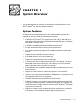
&+$37(5 6\VWHP 2YHUYLHZ This chapter provides an overview of the features and specifications of the Dell® Latitude® CP and CPi portable computers. 6\VWHP )HDWXUHV In addition to the standard features found in a Dell portable computer, the Latitude CP and CPi include the following new features: A Mobile Intel® Pentium® II microprocessor 233, 266, or 300 MHz or an Intel Pentium microprocessor with MMX technology 166, 200, or 233 MHz, with 32 KB of internal cache.
Two power management modessuspend mode (or standby mode in Windows 98) and suspend-to-disk modethat help you conserve battery power. Automatic thermal management that slows the microprocessor or starts a small fan when necessary. An infrared port compatible with IrDA 1.1 (Fast IR) and 1.0 standards, and a USB connector that supports stand-alone and hub devices. A PC Card slot with two connectors that support 5-V and 3.3-V PC Cards.
fan outlet parallel connector speaker USB connector docking connector door docking connector security cable slot hard-disk drive serial connector monitor connector PS2 connector PC Card slot infrared port )LJXUH %DFN 9LHZ RI WKH &RPSXWHU memory module cover modular bay latch battery bay latch hard-disk drive )LJXUH %RWWRP 9LHZ RI WKH &RPSXWHU System Overview 1-3
,QGLFDWRU 3DQHO power indicator numbers lock indicator drive activity indicator capitals lock indicator battery indicator scroll lock indicator )LJXUH ,QGLFDWRU 3DQHO The Latitude CP or CPi computer has three indicators on the display assembly’s indicator panel and three on the keyboard assembly. The following subsections describe the functions of these indicators. 3RZHU ,QGLFDWRU The power indicator is a green LED.
The system supports two low-battery warning codes: The first low-battery warning occurs when the main battery has 15 minutes or less of charge remaining. The amber battery indicator blinks once per second. The second low-battery warning occurs when the main battery has 5 minutes or less of charge remaining. The amber battery indicator lights up without blinking. If no user activity occurs within 15 seconds, the system automatically enters suspend (or standby mode for Windows 98) or suspend-to-disk.
,QWHUUXSW $VVLJQPHQWV 7DEOH ,QWHUUXSW $VVLJQPHQWV 1-6 ,54 /LQH 8VHG $YDLODEOH IRQ0 Generated by the system timer IRQ1 Generated by the keyboard controller to signal that the keyboard output buffer is full IRQ2 Generated internally by the interrupt controller to enable IRQ8 through IRQ15 IRQ3 Available for use by a PC Card unless the built-in serial port or infrared port is configured for COM2 (the default) or COM4 IRQ4 Available for use by a PC Card unless the built-in serial port or infra
7HFKQLFDO 6SHFLILFDWLRQV 7DEOH 7HFKQLFDO 6SHFLILFDWLRQV 0LFURSURFHVVRU Microprocessor: Latitude CPi D300XT Latitude CPi D266XT Latitude CPi D233ST . . . . . . . . Latitude CP M233XT Latitude CP M233ST Latitude CP M233SD Latitude CP M166ST . . . . . . . . Mobile Intel Pentium II microprocessor 300, 266, or 233 MHz Intel Pentium microprocessor with MMX technology 233 or 166 MHz Bus architecture . . . . . . . . . . . . . . . PCI Internal cache memory . . . . . . . . .
7DEOH 7HFKQLFDO 6SHFLILFDWLRQV FRQWLQXHG 3& &DUG PC Card controller . . . . . . . . . . . . . Texas Instruments PCI1131 CardBus controller PC Card connectors . . . . . . . . . . . . two (supports type I and type II cards in any combination; supports type III cards only in the lower connector)1 Cards supported . . . . . . . . . . . . . . 3.3-V and 5-V cards PC Card connector size . . . . . . . . . 68 pins Data width (maximum): PCMCIA . . . . . . . . . . . . . . . . . . 16 bits CardBus . . .
7DEOH 7HFKQLFDO 6SHFLILFDWLRQV &RQQHFWRUV FRQWLQXHG FRQWLQXHG Infrared . . . . . . . . . . . . . . . . . . . . . one port compatible with IrDA Standards 1.1 (Fast IR) and 1.0 (Slow IR) Audio . . . . . . . . . . . . . . . . . . . . . . . microphone-in; line-in/audio-in; headphones/speakers Docking . . . . . . . . . . . . . . . . . . . . . one 200-pin connector for Latitude C/Port APR or C/Dock Expansion Station Universal Serial Bus . . . . . . . . . . . .
7DEOH 7HFKQLFDO 6SHFLILFDWLRQV FRQWLQXHG 'LVSOD\ 'HOO /DWLWXGH &3L ' 67 &3 0 67 DQG &3 0 67 Type . . . . . . . . . . . . . . . . . . . . . . . . active-matrix color (TFT) Dimensions (active area): Height . . . . . . . . . . . . . . . . . . . 184.5 mm (7.26 inches) Width . . . . . . . . . . . . . . . . . . . . 246.0 mm (9.68 inches) Diagonal . . . . . . . . . . . . . . . . . . 307.5 mm (12.10 inches) Maximum resolution/colors . . . . . .
7DEOH 7HFKQLFDO 6SHFLILFDWLRQV FRQWLQXHG 'LVSOD\ 'HOO /DWLWXGH &3 0 6' Type . . . . . . . . . . . . . . . . . . . . . . . HPHC dual-scan color (STN) Dimensions (active area): Height . . . . . . . . . . . . . . . . . . . 184.5 mm (7.26 inches) Width . . . . . . . . . . . . . . . . . . . . 246.0 mm (9.68 inches) Diagonal . . . . . . . . . . . . . . . . . . 307.5 mm (12.10 inches) Maximum resolution/colors . . . . . . 800 x 600 pixels; 262,144 colors Response time (typical) . . . . . . . .
7DEOH 7HFKQLFDO 6SHFLILFDWLRQV FRQWLQXHG .H\ERDUG Number of keys . . . . . . . . . . . . . . . 87 (U.S., Canada, Korea, Thailand, and locations that use traditional Chinese); 88 (Europe); 90 (Japan) Key travel . . . . . . . . . . . . . . . . . . . . 3.0 mm + 0.5 mm/-0.2 mm (0.12 inch + 0.02 inch/-0.008 inch) Key spacing . . . . . . . . . . . . . . . . . . 19.05 mm ± 0.3 mm (0.75 inch ± 0.012 inch) Layout . . . . . . . . . . . . . . . . . . . . . . QWERTY, AZERTY, Kanji %DWWHU\ Type . . . . .
7DEOH 7HFKQLFDO 6SHFLILFDWLRQV FRQWLQXHG $& $GDSWHU Input voltage . . . . . . . . . . . . . . . . . 90 to 135 VAC and 164 to 264 VAC Input current (maximum) . . . . . . . . 3.5 A Input frequency . . . . . . . . . . . . . . . 47 to 63 Hz Output current . . . . . . . . . . . . . . . . 4.5 A (maximum at 4-sec pulse); 3.51 A (continuous) Rated output voltage . . . . . . . . . . . 20.0 VDC Height . . . . . . . . . . . . . . . . . . . . . . 27.9 mm (1.09 inches) Width . . . . . . . . . . . . .
7DEOH 7HFKQLFDO 6SHFLILFDWLRQV FRQWLQXHG 3K\VLFDO 'HOO /DWLWXGH &3 0 6' Height . . . . . . . . . . . . . . . . . . . . . . 38.6 mm (1.52 inches) Width . . . . . . . . . . . . . . . . . . . . . . 306.0 mm (12.05 inches) Depth . . . . . . . . . . . . . . . . . . . . . . 241.0 mm (9.49 inches) Weight6 . . . . . . . . . . . . . . . . . . . . . 2.6 kg (5.8 lb) (QYLURQPHQWDO Temperature: Operating . . . . . . . . . . . . . . . . . 0° to 40°C (32° to 104°F) Storage . . . . . . . . . . . . . .
&+$37(5 ,QLWLDO 3URFHGXUHV This chapter describes initial procedures that can help you diagnose a computer problem. These procedures can often reveal the source of a problem or indicate the correct starting point for troubleshooting the computer. Dell recommends that you perform these procedures in the order presented here. ,QLWLDO 8VHU &RQWDFW When you first contact a user who has a computer problem, ask the user to describe the problem and the conditions under which it occurs.
9LVXDO ,QVSHFWLRQ The visual inspection consists of a quick inspection of the exterior of the computer and any attached peripherals, including making any necessary corrections. For information about the proper removal and installation of computer components, as instructed in the following procedures, see Chapter 4, “Removing and Replacing Parts.
,I WKH FRPSXWHU LV GRFNHG LQ D & 3RUW $GYDQFHG 3RUW 5HSOLFDWRU $35 RU & 'RFN ([SDQVLRQ 6WDWLRQ XQGRFN WKH FRPSXWHU See the User's Guide that came with the C/Port APR or C/Dock Expansion Station for detailed instructions on undocking the computer. 9HULI\ WKDW WKH H[WHULRU RI WKH FRPSXWHU LV IUHH RI REYLRXV SK\VLFDO GDPDJH ,I WKH FRPSXWHU LV RSHUDWLQJ IURP DQ $& DGDSWHU YHULI\ WKH IROORZLQJ The AC adapter’s AC power cable is connected to both the adapter and a power source.
,I DQ H[WHUQDO PRQLWRU LV FRQQHFWHG YHULI\ WKH IROORZLQJ The monitor’s interface cable is properly attached to the video connector on the I/O panel. The captive screws that secure the connectors at each end of the interface cable are secure enough to ensure a firm connection. The monitor’s power cable is attached to a power source and free of obvious physical damage. The monitor’s controls are set according to the instructions in the documentation for the monitor.
To observe the boot routine, follow these steps: 7XUQ RII WKH FRPSXWHU DQG DQ\ DWWDFKHG SHULSKHUDOV ,I QHFHVVDU\ LQVWDOO D GLVNHWWH GULYH LQ WKH PHGLD ED\ ,QVHUW D GLDJQRVWLFV GLVNHWWH LQWR WKH GLVNHWWH GULYH 7XUQ RQ DOO SHULSKHU DOV DQG WKHQ WKH FRPSXWHU :DWFK WKH LQGLFDWRUV RQ WKH WRS RI WKH NH\ERDUG $IWHU DOO WKUHH LQGLFDWRUV IODVK PRPHQWDULO\ WKH 1XP /RFN LQGLFDWRU VKRXOG OLJKW XS DQG UHPDLQ RQ Do these indicators light up within approximately 10 seconds after the boot routine st
(OLPLQDWLQJ 5HVRXUFH &RQIOLFWV Devices within the computer may require dedicated memory spaces, interrupt levels, or DMA channels, all of which must be allocated during installation of the devices. Because devices may be installed at different times, it is possible that the same resource is assigned to two or more devices. Resource conflicts can result in disorderly or erratic computer operation or failure of the computer to operate at all.
&+$37(5 6\VWHP (UURU 0HVVDJHV This chapter describes system error messages that can occur during computer startup or, in the case of some failures, during normal computer operation. The tables in this chapter list POST error codes, battery failure codes, and system error messages, as well as their probable causes. If a faulty computer does not display a POST error code or system error message to indicate a failure, use the Dell Diagnostics to help isolate the source of the problem.
7DEOH 3267 (UURU &RGHV ,QGLFDWRU &RGH 3-2 (UURU 3UREDEOH &DXVHV 1-1-3 NVRAM write/read failure BIOS corrupted; system board faulty 1-1-4 ROM BIOS checksum failure BIOS corrupted; system board faulty 1-2-1 Programmable interval timer failure System board faulty 1-2-2 DMA initialization failure System board faulty 1-2-3 DMA page register write/read failure System board faulty 1-3-1 through 1-1-1 Installed memory module(s) not being properly identified or used Memory module improperl
7DEOH 3267 (UURU &RGHV ,QGLFDWRU &RGH FRQWLQXHG (UURU 3UREDEOH &DXVHV 4-3-1 Memory failure above address 0FFFFh Memory module improperly seated or system memory controller faulty (system board faulty) 4-3-3 Timer chip counter 2 failure System board faulty 4-3-4 Time-of-day clock stopped Reserve battery faulty or system board faulty 4-4-1 Serial port failure System board faulty 5-1-2 No usable memory Memory module improperly seated or system memory controller faulty (system board faul
%DWWHU\ )DLOXUH &RGHV In the event of a battery failure, the battery indicator displays indicator codes that identify the severity of the problem. The following table lists these failure codes. 7DEOH %DWWHU\ )DLOXUH &RGHV %DWWHU\ ,QGLFDWRU &RGH 6HYHULW\ RI )DLOXUH 3UREDEOH &DXVHV $FWLRQ Indicator flashes alternately green and amber.
6\VWHP (UURU 0HVVDJHV The following table lists (in alphabetical order) system error messages that may appear on the display during the boot routine or during normal computer operation. 7DEOH 6\VWHP (UURU 0HVVDJHV 0HVVDJH 'HILQLWLRQ 3UREDEOH &DXVHV Auxiliary device failure Integrated touch pad or external PS/2 mouse failed. Integrated touch pad or external PS/2 mouse faulty. Bad command or File Name Command entered does not exist or is not in pathname specified.
7DEOH 6\VWHP (UURU 0HVVDJHV FRQWLQXHG 0HVVDJH 'HILQLWLRQ 3UREDEOH &DXVHV Diskette writeprotected Diskette is writeprotected; operation cannot be completed. Diskette writeprotected. Drive not ready The diskette may be missing from or improperly installed in the diskette drive. Defective or unformatted diskette. Error reading PCMCIA card Computer cannot identify PC Card. PC Card faulty, improperly seated, or improperly configured. System board faulty.
7DEOH 6\VWHP (UURU 0HVVDJHV FRQWLQXHG 0HVVDJH 'HILQLWLRQ 3UREDEOH &DXVHV Invalid configuration information — please run System Setup program System Setup contains invalid settings. System Setup program contains incorrect settings. Keyboard controller failure Keyboard controller not responding. Cable or connector loose, or keyboard faulty. Keyboard clock line failure Keyboard not responding. Cable or connector loose, or keyboard faulty. Keyboard key(s) jammed.
7DEOH 6\VWHP (UURU 0HVVDJHV FRQWLQXHG 0HVVDJH 'HILQLWLRQ 3UREDEOH &DXVHV Memory data line failure at address, read value expecting value Memory not operating properly. Installed memory module faulty or improperly seated. No boot device available Computer not recognizing diskette drive or hard-disk drive from which it is trying to boot. No boot device available. No boot sector on hard-disk drive No boot sector on harddisk drive. Operating system boot files missing or corrupted.
7DEOH 6\VWHP (UURU 0HVVDJHV FRQWLQXHG 0HVVDJH 'HILQLWLRQ 3UREDEOH &DXVHV Seek error MS-DOS unable to find specific track on diskette or hard-disk drive. Defective diskette or hard-disk drive. Shutdown failure Microprocessor unable to reset. System board faulty. Time-of-day clock lost power System clock stopped. Reserve battery lost its charge. Time-of-day not set—please run the System Setup program. Time or date stored in RTC does not match system clock. Reserve battery lost its charge.
SCSI Devices — Tests the SCSI controller in the C/Port APR or the C/Dock Expansion Station Network Interface — Tests the network controller in the C/Port APR or the C/Dock Expansion Station Audio — Tests the built-in sound subsystem Other — Tests the cooling fan, which works with the air intake on the computer as part of the automatic thermal management system.
&+$37(5 5HPRYLQJ DQG 5HSODFLQJ 3DUWV This chapter provides instructions for removing and replacing fieldreplaceable components, assemblies, and subassemblies. Unless otherwise noted, each procedure in this chapter assumes the following: The computer and any attached peripherals are turned off, and the peripherals are disconnected from the I/O panel on the back of the computer. A part can be replaced by performing the removal procedure in reverse order.
5HFRPPHQGHG 7RROV Most of the procedures in this guide require the use of one or more of the following tools: Number 1 magnetized Phillips-head screwdriver Small flat-blade screwdriver Small plastic scribe 3UHFDXWLRQDU\ 0HDVXUHV :$51,1* )RU \RXU SHUVRQDO VDIHW\ DQG SURWHFWLRQ RI WKH HTXLS PHQW SHUIRUP WKH IROORZLQJ VWHSV LQ WKH VHTXHQFH OLVWHG Before you start to work on the computer, perform the following steps: 7R DYRLG SRVVLEOH GDPDJH WR WKH FRPSXWHU IURP (6' SHULRGLFDOO\ JURXQG \RXUVHOI
5HPRYH WKH PDLQ EDWWHU\ DVVHPEO\ IURP WKH EDWWHU\ ED\ Slide the battery bay latch away from the center of the computer. Then slide the battery out of the battery bay (see Figure 4-2).
=,) &RQQHFWRUV movable part of connector (do not remove) )LJXUH 'LVFRQQHFWLQJ DQ ,QWHUIDFH &DEOH Some of the computer’s interface connectors are zero insertion force (ZIF) connectors.
)LHOG 5HSODFHDEOH 3DUWV DQG $VVHPEOLHV Table 4-1 lists the parts and assemblies available for the computer. Some parts may only be available as part of a service kit or assembly, and are provided for reference only. The subsections that follow Table 4-1 provide instructions for removing and replacing these parts and assemblies.
7DEOH 3DUWV DQG $VVHPEOLHV 3DUW RU $VVHPEO\ 1DPH FRQWLQXHG 2UGHU 1DPH )LJXUH %RWWRP &DVH $VVHPEO\ Bottom case assembly ASSY,CVR,BTM,PLSTC, BASE,CP 4-5, 4-24 %RWWRP &DVH %UDFNHW Bottom case bracket assembly ASSY,BRKT,CASE,BTM 4-27 &' 520 'ULYH 6XEDVVHPEO\ Service kit, CD-ROM drive SVC,SUBASSY,CD,20X, NBK,SANYO CD-ROM drive bezel BZL,CD 20X CD-ROM drive CD,680M,10X,INT,NBK CD-ROM drive interface board PWA,CD/FDD INTERCONN,SE Bottom CD-ROM drive cover CVR,BTM,PLSTC,CD,CP Top CD-ROM
7DEOH 3DUWV DQG $VVHPEOLHV 3DUW RU $VVHPEO\ 1DPH FRQWLQXHG 2UGHU 1DPH )LJXUH +DUG 'LVN 'ULYH $VVHPEOLHV SUBASSY,HD,xxxxx,I,yyyMM, CP* Hard-disk drive, subassembly Hard-disk drive HD,xxxxx,I,yyMM,NBK,zzz* Hard-disk drive interface board PWA,INTERCONN,HD,CP Hard-disk drive bracket BRKT,HD,CP 4-6 +DUG 'LVN 'ULYH %UDFNHW 'RRU $VVHPEO\ Hard-disk drive carrier bracket/ door assembly service kit SVC,ASSY,BRKT/DOOR, HD,CP Hard-disk drive carrier door DOOR,HD,12.
7DEOH 3DUWV DQG $VVHPEOLHV 3DUW RU $VVHPEO\ 1DPH FRQWLQXHG 2UGHU 1DPH .H\ERDUGV )LJXUH FRQWLQXHG Keyboard, Russian KYBD,87,RUS,CP Keyboard, Spanish KYBD,88,SPN,CP Keyboard, Swedish/Finnish KYBD,88,SWE,CP Keyboard, Swiss KYBD,88,SWI,CP Keyboard, Thailand KYBD,87,THAI,CP Keyboard, U.K. KYBD,88,UK,CP Keyboard, U.S. KYBD,87,DOM,CP /&' $VVHPEOLHV ,QFK 'LVSOD\ Bezel service kit, 12.1-inch display Display assembly bezel BZL,LCD,TFT,12.
7DEOH 3DUWV DQG $VVHPEOLHV 3DUW RU $VVHPEO\ 1DPH FRQWLQXHG 2UGHU 1DPH /&' $VVHPEOLHV ,QFK 'LVSOD\ LCD/Cable service kit, Samsung )LJXUH FRQWLQXHG SVC,LCD/CBL/INV, TFT,SMSNG,CP LCD inverter board subassembly SUBASSY,PWA,INVRTR W/INSUL,LCD,CP LCD cable subassembly, Samsung SUBASSY,CBL/HLDR,TFT, SMSNG,CP LCD panel, Samsung LCD,TFT,SVGA,12.
7DEOH 3DUWV DQG $VVHPEOLHV 3DUW RU $VVHPEO\ 1DPH FRQWLQXHG 2UGHU 1DPH /&' $VVHPEOLHV ,QFK ;*$ 'LVSOD\ Display top cover service kit, 13.3-inch display )LJXUH FRQWLQXHG SVC,CVR,TOP,LCD,13.3” Display top cover CVR,LCD,TOP,TFT,13.3” Display top-cover shield SHLD,EMI,DIS,TFT,13.3” LCD/Cable service kit, Samsung SVC,LCD/CBL/INV,SMSNG, CPX LCD inverter board PWA,INVRTR,LCD,13.3”,CPX LCD inverter board shield SHLD,INVRTR,LCD,MYLAR, 13.
7DEOH 3DUWV DQG $VVHPEOLHV 3DUW RU $VVHPEO\ 1DPH FRQWLQXHG 2UGHU 1DPH )LJXUH /&' 3DUWV 0LVFHOODQHRXV Left hinge, 12.1-inch display HNG,LF,LCD,TFT/STN,12.1” Right hinge, 12.1-inch display HNG,RT,LCD,TFT/STN,12.1” Left hinge, 13.3-inch display HNG,LF,LCD,TFT,13.3” Right hinge, 13.3-inch display HNG,RT,LCD,TFT,13.3” Right bracket, 12.1-inch display BRKT,RT,LCD,TFT/STN Reed switch magnet, 12.1-inch display SWT,SUS,MGNT,DSPL, TFT/STN Plastic inverter-board screw caps, 12.
7DEOH 3DUWV DQG $VVHPEOLHV 3DUW RU $VVHPEO\ 1DPH FRQWLQXHG 2UGHU 1DPH 6FUHZV )LJXUH LCD panel SCR,M3X5,PHH,LP,ZPS 4-18, 4-19 LCD hinge SCR,M3X5,PHH,LP,ZPS 4-16 LCD inverter board SCR,M3X5,PHH,LP,ZPS 4-21 LCD bezel and latch, 12.1-inch display SCR,M3X5,PHH,LP,ZPS 4-17 Keyboard SCR,M2.6X12,PHH,LP,ZPS 4-9 Thermal cooling assembly SCR,M2X2.5,PHH,LP,ZPS 4-30 Touch-pad SCR,M2.6X1.8,PHH,XLP,ZPS 4-13 Palmrest, front edge SCR,M2.
7DEOH 3DUWV DQG $VVHPEOLHV FRQWLQXHG 3DUW RU $VVHPEO\ 1DPH 2UGHU 1DPH 6\VWHP %RDUG $VVHPEO\ FRQWLQXHG System board assembly with system board and processor module ASSY,PRM/PWA,ENGINE, CPixxx* System-board engine subassembly SUBASSY,PWA/ENGINE,CP I/R board PWA,FAST IR,CP Microphone boot GRMT,RBR,BOOT,MCPHN Main system board PWA,PLN,0M,NB,CP Video/PC Card board PWA,DTRBD,VID/PCMCIA,CP LED board PWA,LED,CP Lower EMI shield SHLD,BTM,PLN ASSY,CP Upper EMI shield, 1st SHLD,TOP,1ST,PLN ASSY
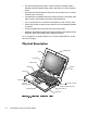
5HPRYLQJ )LHOG 5HSODFHDEOH 3DUWV DQG $VVHPEOLHV display assembly keyboard palmrest assembly back cover assembly main battery bottom case assembly modular bay device )LJXUH ([SORGHG 9LHZ³&RPSXWHU The following subsections provide instructions for removing and replacing field-replaceable parts and assemblies.
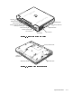
+DUG 'LVN 'ULYH $VVHPEO\ bottom of computer 5-mm screws (2) hard-disk drive door )LJXUH +DUG 'LVN 'ULYH $VVHPEO\ 5HPRYDO 7XUQ WKH FRPSXWHU RYHU DQG UHPRYH WKH WZR PP VFUHZV IURP WKH KDUG GLVN GULYH GRRU The drive is on the left side of the computer.
0HPRU\ 0RGXOH &RYHU indentation memory module cover )LJXUH 0HPRU\ 0RGXOH &RYHU 5HPRYDO &$87,21 0DNH VXUH WKH ZRUN VXUIDFH LV FOHDQ WR SUHYHQW VFUDWFKLQJ WKH FRPSXWHU FRYHU &ORVH WKH GLVSOD\ DQG WXUQ WKH FRPSXWHU XSVLGH GRZQ RQ D IODW ZRUN VXUIDFH 5HOHDVH WKH PHPRU\ PRGXOH FRYHU Insert a fingertip in the indentation in the bottom case assembly and lift the cover slightly; then slide the cover in the direction indicated by the arrow on the cover.
0HPRU\ 0RGXOHV memory module sockets (2) retaining clips (2 per socket) )LJXUH 0HPRU\ 0RGXOH 5HPRYDO 5HPRYH WKH PHPRU\ PRGXOH FRYHU 7R DYRLG SRVVLEOH GDPDJH WR WKH PHPRU\ PRGXOH IURP (6' JURXQG \RXUVHOI E\ WRXFKLQJ WKH PHWDO VXUIDFH RI DQ , 2 FRQQHFWRU RQ WKH FRPSXWHU·V EDFN SDQHO 7R UHOHDVH D PHPRU\ PRGXOH IURP LWV VRFNHW JHQWO\ SXVK RXWZDUG RQ HDFK RI WKH PHPRU\ PRGXOH·V WZR PHWDO UHWDLQLQJ FOLSV The memory module should rotate upward out of its retaining clips.
.H\ERDUG $VVHPEO\ To remove the keyboard assembly, follow these steps: &$87,21 0DNH VXUH WKH ZRUN VXUIDFH LV FOHDQ WR SUHYHQW VFUDWFKLQJ WKH FRPSXWHU FRYHU &ORVH WKH GLVSOD\ DVVHPEO\ DQG WXUQ WKH FRPSXWHU XSVLGH GRZQ RQ D IODW ZRUN VXUIDFH VHH )LJXUH 12-mm screws (6) )LJXUH 5HPRYLQJ WKH .
metal tabs (2) keyboard plastic tabs (2) scalloped edge of blank key palmrest deflect palmrest outward to release keyboard )LJXUH .H\ERDUG $VVHPEO\ 5HPRYDO 2QFH WKH NH\ERDUG LV IXOO\ UHOHDVHG IURP WKH SDOPUHVW SODFH WKH NH\ERDUG XSVLGH GRZQ RYHU WKH WRXFK SDG 'LVFRQQHFW WKH NH\ERDUG FDEOH IURP FRQQHFWRU .% RQ WKH V\VWHP ERDUG 5HPRYH WKH NH\ERDUG DVVHPEO\ Follow these steps when replacing the keyboard assembly: &RQQHFW WKH NH\ERDUG FDEOH WR FRQQHFWRU .
%DFN &RYHU $VVHPEO\ 5-mm screws (12) )LJXUH %DFN &RYHU $VVHPEO\ 5HPRYDO &ORVH WKH GLVSOD\ 5HPRYH WKH WZHOYH PP VFUHZV VHFXULQJ WKH EDFN FRYHU Five screws on the underside of the back cover One screw behind the docking connector door Six screws on the face of the back cover &ORVH WKH GRFNLQJ FRQQHFWRU GRRU 5HPRYH WKH EDFN FRYHU DVVHPEO\ Grasp the right end of the back cover assembly firmly, and unsnap it from the computer.
3DOPUHVW $VVHPEO\ The palmrest assembly consists of the touch pad and the palmrest.
7XUQ WKH FRPSXWHU ULJKW VLGH XS RQ WKH ZRUN VXUIDFH DQG RSHQ WKH GLVSOD\ DVVHPEO\ GHJUHHV NOTE: Support the display assembly with a book or similar object so that the display assembly does not open beyond 180 degrees. &DUHIXOO\ UHPRYH WKH SDOPUHVW DVVHPEO\ IURP WKH ERWWRP FDVH DVVHPEO\ The palmrest assembly is secured in the bottom case assembly by four snaps and tabs on the right and left ends of the palmrest. Take care not to damage the snaps when removing the palmrest.
7RXFK 3DG ,QWHUIDFH 0RGXOH 1.
3RZHU %XWWRQ 5HPRYH WKH SDOPUHVW DVVHPEO\ 7XUQ WKH SDOPUHVW DVVHPEO\ XSVLGH GRZQ RQ D IODW ZRUN VXUIDFH &RPSUHVV WKH WZR FDWFKHV VHFXULQJ WKH SRZHU EXWWRQ DQG UHPRYH WKH SRZHU EXWWRQ DQG VSULQJ IURP WKH SDOPUHVW DVVHPEO\ 4-24 Dell Latitude CP and CPi Service Manual
'LVSOD\ $VVHPEO\ &RPSRQHQWV For removal purposes, the display assembly consists of the following components: Display assembly bezel LCD panel LCD inverter board LCD inverter board shield (13.3-inch display only) Display-assembly interface cable Display assembly latch Display assembly top-cover assembly Display assembly hinges Display assembly right bracket (12.
display assembly bezel LCD panel display assembly latch display-assembly interface cable LCD inverter board shield display-assembly top-cover assembly hinge (2) )LJXUH ([SORGHG 9LHZ³'LVSOD\ $VVHPEO\ ,QFK 'LVSOD\ 6KRZQ 4-26 Dell Latitude CP and CPi Service Manual LCD inverter board
'LVSOD\ $VVHPEO\ display assembly 5-mm screws (4) display-assembly interface-cable grounding screws (2) display-assembly interface cable hinges (2) )LJXUH 'LVSOD\ $VVHPEO\ 5HPRYDO 5HPRYH WKH SDOPUHVW DVVHPEO\ 5HPRYH WKH WZR PP LQWHUIDFH FDEOH JURXQGLQJ VFUHZV IURP WKH GLVSOD\ DVVHPEO\ LQWHUIDFH FDEOH 'LVFRQQHFW WKH GLVSOD\ DVVHPEO\ LQWHUIDFH FDEOH IURP FRQQHFWRU -3 RQ WKH V\VWHP ERDUG Grasp the grounding tabs and pull the connector straight up from the system board.
5HPRYH WKH IRXU VLOYHU PP VFUHZV VHFXULQJ HDFK RI WKH WZR KLQJH EUDFNHWV WR WKH ERWWRP FDVH DVVHPEO\ /LIW WKH GLVSOD\ DVVHPEO\ IURP WKH ERWWRP FDVH DVVHPEO\ NOTE: When reinstalling the display assembly, install the four screws securing the hinges at the locations marked by arrows on the face of each hinge.
'LVSOD\ $VVHPEO\ %H]HO l 5-mm screws (4) (12.1-inch displays); 3-mm screws (4) (13.3-inch displays) screw covers (6) display assembly bezel 5-mm screws (2) display-assembly top cover )LJXUH 'LVSOD\ $VVHPEO\ %H]HO 5HPRYDO ,QFK 'LVSOD\ 6KRZQ 8VH D VFULEH WR FDUHIXOO\ SU\ WKH VFUHZ FRYHUV RXW RI WKH VL[ VFUHZ KROHV LQ WKH EH]HO 5HPRYH WKH VL[ VFUHZV IURP WKH EH]HO On 12.1-inch displays, all six screws are 5-mm screws. On 13.
'LVSOD\ $VVHPEO\ /DWFK 5HPRYH WKH GLVSOD\ DVVHPEO\ EH]HO 5HPRYH WKH GLVSOD\ DVVHPEO\ ODWFK a. If replacing the latch in a 12.1-inch display, lift the display assembly latch straight up from the display-assembly top cover. b. If replacing the latch in a 13.3-inch display, unsnap the latch and captive spring from the inside of the display assembly top-cover assembly.
/&' 3DQHO The following subsections describe how to remove an LCD panel.
NOTE: When replacing the LCD panel, ensure that the tabs on the display-assembly EMI shield fit over the four LCD panel mounting bosses. (This is necessary for adequate grounding of the LCD panel.
'LVFRQQHFW WKH GLVSOD\ DVVHPEO\ LQWHUIDFH FDEOH IURP WKH =,) FRQ QHFWRU RQ WKH XQGHUVLGH RI WKH /&' SDQHO To disconnect the cable, carefully work the cable connector free from the ZIF connector on the LCD panel. Do not pull on the LCD interface cable itself. %HIRUH UHSODFLQJ WKH /&' SDQHO HQVXUH WKDW WKH FRUUHFW PDJQHW LV LQVWDOOHG LQ WKH PDJQHW KROGHU A magnet switch causes the computer to go into suspend mode when the display is closed.
Samsung LCD Panel Place a single, small magnet and a foam spacer in the magnet holder, as shown in Figure 4-20. Place the magnet to the left of the foam spacer, assuming you are facing the display as shown in Figure 4-19. magnet foam spacer )LJXUH 0DJQHW +ROGHU NOTE: When replacing the LCD panel, ensure that the tabs on the display-assembly EMI shield fit over the four LCD-panel mounting bosses. (This is necessary for adequate grounding of the LCD panel.
/&' ,QYHUWHU %RDUG The following subsections describe how to remove an LCD inverter board from a 12.1-inch or 13.3-inch LCD display.
,QFK /&' 'LVSOD\ display-assembly top cover interface cable top cover brace LCD inverter board LCD inverter board shield )LJXUH /&' ,QYHUWHU %RDUG 5HPRYDO ,QFK 'LVSOD\ 5HPRYH WKH GLVSOD\ DVVHPEO\ EH]HO 5HPRYH WKH /&' SDQHO 'LVFRQQHFW WKH GLVSOD\ DVVHPEO\ LQWHUIDFH FDEOH IURP =,) FRQQHF WRU - RQ WKH /&' LQYHUWHU ERDUG 6OLGH WKH /&' LQYHUWHU ERDUG RXW RI WKH /&' LQYHUWHU ERDUG VKLHOG NOTE: Replace the LCD inverter board in the shield so that the components on the board fac
'LVSOD\ $VVHPEO\ ,QWHUIDFH &DEOH 5-mm screws (2) display-assembly interface cable left hinge plastic bobbin connector J1 )LJXUH 'LVSOD\ $VVHPEO\ ,QWHUIDFH &DEOH 5HPRYDO ,QFK 'LVSOD\ 6KRZQ 5HPRYH WKH GLVSOD\ DVVHPEO\ 5HPRYH WKH /&' SDQHO 'LVFRQQHFW WKH GLVSOD\ DVVHPEO\ LQWHUIDFH FDEOH IURP =,) FRQQHF WRU - RQ WKH /&' LQYHUWHU ERDUG 5HPRYH WKH WZR PP VFUHZV VHFXULQJ WKH OHIW KLQJH DQG WKHQ UHPRYH WKH KLQJH IURP WKH GLVSOD\ DVVHPEO\ WRS FRYHU ,I \RX DUH UHPRYLQJ WKH GLVSO
/&' 'LVSOD\ +LQJH 5HPRYH WKH /&' GLVSOD\ DVVHPEO\ IURP WKH FRPSXWHU 5HPRYH WKH GLVSOD\ DVVHPEO\ EH]HO 5HPRYH WKH IRXU VLOYHU PP VFUHZV VHFXULQJ WKH WZR KLQJH EUDFNHWV WR WKH GLVSOD\ DVVHPEO\ WRS FRYHU NOTES: To aid in reinstalling the hinges and display assembly, the right and left hinges are marked by an “R” and an “L,” respectively. Install the four screws securing the hinges at the locations marked by arrows on the face of each hinge. The right bracket on a 12.
'LVSOD\ $VVHPEO\ 7RS &RYHU 5HPRYH WKH GLVSOD\ DVVHPEO\ EH]HO 5HPRYH WKH GLVSOD\ DVVHPEO\ 5HPRYH WKH /&' SDQHO 5HPRYH WKH /&' LQYHUWHU ERDUG 5HPRYH WKH GLVSOD\ DVVHPEO\ ODWFK 5HPRYH WKH OHIW DQG ULJKW KLQJHV 5HPRYH WKH ULJKW EUDFNHW LQFK GLVSOD\ RQO\ 5HPRYH WKH GLVSOD\ DVVHPEO\ LQWHUIDFH FDEOH ,I \RX DUH UHPRYLQJ WKH GLVSOD\ DVVHPEO\ WRS FRYHU IURP D LQFK GLVSOD\ UHPRYH WKH ULJKW DQG OHIW EUDFHV To remove a brace, remove the 3-mm screw securing the brace to t
%RWWRP &DVH $VVHPEO\ The bottom case assembly consists of the following field-replaceable components: Diskette drive assembly, CD-ROM drive assembly, or travel module Back cover assembly Audio shield Audio board Bottom case bracket Module latch assemblies Speakers System board assembly Thermal cooling assembly Air flow duct Exhaust fan I/R board Reserve battery 4-40 Dell Latitude CP and CPi Service Manual
audio board audio shield thermal cooling assembly I/R board system board assembly bottom case bracket air flow duct module latch assembly (2) main battery modular bay device )LJXUH %RWWRP &DVH $VVHPEO\ Removing and Replacing Parts 4-41
0RGXODU %D\ 'HYLFHV 'LVNHWWH 'ULYH &' 520 'ULYH %DWWHU\ RU 7UDYHO 0RGXOH latch lock )LJXUH 0RGXODU %D\ 'HYLFH 5HPRYDO NOTE: You do not need to remove the main battery or hard-disk drive prior to this procedure. &$87,21 0DNH VXUH WKH ZRUN VXUIDFH LV FOHDQ WR SUHYHQW VFUDWFKLQJ WKH FRPSXWHU FRYHU &ORVH WKH GLVSOD\ DQG WXUQ WKH FRPSXWHU RYHU 5HPRYH WKH GHYLFH IURP WKH PRGXODU ED\ Push the modular bay latch away from the center of the computer.
$XGLR 6KLHOG 5HPRYH WKH SDOPUHVW DVVHPEO\ 5HPRYH WKH PP VFUHZ VHFXULQJ WKH DXGLR ERDUG VKLHOG VHH )LJ XUH 5HPRYH WKH DXGLR ERDUG VKLHOG NOTE: When replacing the audio shield, ensure that the audio shield is properly seated to prevent it from cutting into the speaker wires or interfering with devices installed in the modular bay. (You can check this by temporarily installing a device in the modular bay prior to reinstalling the palmrest assembly.
$XGLR %RDUG 5-mm screw audio shield audio board speaker wires )LJXUH $XGLR %RDUG 5HPRYDO 5HPRYH WKH SDOPUHVW DVVHPEO\ 5HPRYH WKH PP VFUHZ VHFXULQJ WKH DXGLR ERDUG VKLHOG 5HPRYH WKH DXGLR ERDUG VKLHOG 'LVFRQQHFW WKH VSHDNHU ZLUHV DQG PLFURSKRQH ZLUHV IURP WKHLU FRQQHFWRUV RQ WKH DXGLR ERDUG The connectors are fragile—do not pull on the wires to disconnect them.
%RWWRP &DVH %UDFNHW left speaker wires plastic retaining clip 5-mm screws (4) left speaker slot right speaker )LJXUH %RWWRP &DVH %UDFNHW 5HPRYDO 5HPRYH WKH SDOPUHVW DVVHPEO\ 5HPRYH WKH DXGLR ERDUG VKLHOG 'LVFRQQHFW WKH VSHDNHU ZLUHV IURP FRQQHFWRUV -3 DQG -3 RQ WKH DXGLR ERDUG The connectors are fragile—do not pull on the speaker wires to disconnect them.
0RGXOH /DWFK $VVHPEOLHV module latch assemblies (2) spring (2) module latches (2) )LJXUH 0RGXOH /DWFK $VVHPEOLHV 5HPRYDO 5HPRYH WKH ERWWRP FDVH EUDFNHW 5HPRYH WKH OHIW ODWFK IURP WKH RXWVLGH RI WKH ERWWRP FDVH E\ XQVQDSSLQJ WKH VOLGHU VSULQJ DVVHPEO\ Keep pressure applied to the slider-spring assembly while unsnapping the latch to prevent the slider-spring assembly from coming loose from the case. If the slider-spring assembly does come loose from the case: a.
5HSHDW VWHSV ² IRU WKH ULJKW ODWFK 2Q WKH EDVH SODVWLF ILQG WKH PROGHG ODEHO ´3 1 $66< µ WKHQ XVLQJ D SHUPDQHQW PDUNHU ZULWH ´$ µ WR WKH ULJKW RI ´ µ This revision mark indicates that the latch rework is complete.
6\VWHP %RDUG $VVHPEO\ 2.5-mm screws (2) thermal cooling assembly air flow duct system board assembly 5-mm screws (2) 2.5-mm screw bottom case assembly )LJXUH 6\VWHP %RDUG $VVHPEO\ 5HPRYDO The system board’s BIOS chip contains the system service tag number, which is also visible on a bar-code label on the bottom of the computer.
&$87,21 7R HQVXUH PD[LPXP FRROLQJ IRU WKH PLFURSURFHVVRU GR QRW WRXFK WKH KHDW WUDQVIHU DUHDV RQ WKH WKHUPDO FRROLQJ DVVHPEO\ 7KH RLOV LQ \RXU VNLQ UHGXFH WKH KHDW WUDQVIHU FDSDELOLW\ RI WKH WKHUPDO SDGV 5HPRYH WKH WKHUPDO FRROLQJ VXEDVVHPEO\ IURP WKH PLFUR SURFHVVRU PRGXOH 5HPRYH WKH DLU IORZ GXFW 9HULI\ WKDW WKH 3& &DUG HMHFWRUV GR QRW H[WHQG IURP WKH 3& &DUG ED\ 5HPRYH WKH PP VFUHZ IURP WKH FHQWHU RI WKH FRPSXWHU·V OHIW UHDU IRRW 5HPRYH WKH IROORZLQJ WZR VFUHZV IURP WKH V\VWHP
([KDXVW )DQ exhaust fan power cable connector (JFAN1) 12-mm screws (2) exhaust fan )LJXUH ([KDXVW )DQ 5HPRYDO 5HPRYH WKH SDOPUHVW DVVHPEO\ 'LVFRQQHFW WKH H[KDXVW IDQ SRZHU FDEOH IURP FRQQHFWRU -)$1 RQ WKH V\VWHP ERDUG 5HPRYH WKH WZR PP VFUHZV VHFXULQJ WKH H[KDXVW IDQ DQG WKHQ UHPRYH WKH H[KDXVW IDQ NOTE: When replacing the exhaust fan, orient the fan such that the fan label faces outward and the power cable is at the upper right corner of the fan (when viewed from the back of
, 5 %RDUG 5-mm screw I/R board )LJXUH , 5 %RDUG 5HPRYDO 5HPRYH WKH SDOPUHVW DVVHPEO\ 5HPRYH WKH PP VFUHZ VHFXULQJ WKH , 5 ERDUG WR WKH V\VWHP ERDUG DVVHPEO\ /LIW WKH , 5 ERDUG VWUDLJKW XS IURP WKH V\VWHP ERDUG DVVHPEO\ Removing and Replacing Parts 4-51
5HVHUYH %DWWHU\ reserve battery reserve battery cable connector (JBAT1) )LJXUH 5HVHUYH %DWWHU\ ,QVWDOODWLRQ &$87,21 7KH UHVHUYH EDWWHU\ SURYLGHV SRZHU WR WKH FRPSXWHU·V 57& DQG 195$0 ZKHQ WKH FRPSXWHU LV WXUQHG RII 5HPRYLQJ WKH EDWWHU\ FDXVHV WKH FRPSXWHU WR ORVH LWV GDWH DQG WLPH LQIRUPDWLRQ DV ZHOO DV DOO XVHU VHWWDEOH SDUDPHWHUV LQ 195$0 ,I SRVVLEOH PDNH D FRS\ RI WKLV LQIRUPDWLRQ EHIRUH \RX UHPRYH WKH UHVHUYH EDWWHU\ To remove the reserve battery, follow these steps: 5HPRYH WKH SDOP
,QGH[ $ audio board removal, 4-44 audio shield removal, 4-43 % back cover assembly removal, 4-20 battery (in modular bay) removal, 4-42 battery failure codes about, 3-4 list of, 3-4 battery indicator, 1-4 boot routine observing when troubleshooting, 2-4 bottom case assembly components, 4-40 illustrated, 4-41 bottom case bracket removal, 4-45 computer features, 1-1 illustrated, 1-2, 1-3 power, controlling, 1-5 ' Dell Diagnostics, 3-9 diskette drive removal, 4-42 display assembly bezel, removal, 4-29 com
) LCD panel removal, 4-31, 4-32 field-replaceable parts and assemblies illustrated, 4-14 list of, 4-5 LEDs, 1-4 + hard-disk drive assembly removal, 4-15 help getting, 2-6 , I/O panel, 1-3 I/R board removal, 4-51 low-battery warnings, 1-4 0 main battery assembly removal, 4-3 memory module removal, 4-17 memory module cover removal, 4-16 messages, system error about, 3-5 list of, 3-5 modular bay devices removal, 4-42 indicator panel, 1-4 module latch assemblies removal, 4-46 initial procedures system
6 travel module removal, 4-42 screw identification and tightening, 4-3 troubleshooting boot routine interpretation, 2-4 external visual inspection, 2-2 initial user contact, 2-1 resource conflicts, eliminating, 2-6 sockets memory module, 4-17 speakers removal, 4-47 specifications technical, 1-7 8 subsystems testing, 3-9 user contact initial, 2-1 system features, 1-1 illustrated, 1-2 system board assembly removal, 4-48 system error messages about, 3-5 list of, 3-5 7 9 visual inspection external, 2-
3ULQWHG LQ WKH 8 6 $ ® ZZZ GHOO FRP 3 1 5HY $