
Specifications

vii
Figure 4-3. Screw Identification. . . . . . . . . . . . . . . . . . . . . . . . . . . . . . . . .4-3
Figure 4-4. Disconnecting an Interface Cable . . . . . . . . . . . . . . . . . . . . . .4-4
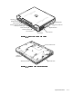
Figure 4-5. Exploded View—Computer. . . . . . . . . . . . . . . . . . . . . . . . . .4-14
Figure 4-6. Hard-Disk Drive Assembly Removal . . . . . . . . . . . . . . . . . . .4-15
Figure 4-7. Memory Module Cover Removal . . . . . . . . . . . . . . . . . . . . .4-16
Figure 4-8. Memory Module Removal. . . . . . . . . . . . . . . . . . . . . . . . . . . 4-17
Figure 4-9. Removing the Keyboard Assembly Screws . . . . . . . . . . . . .4-18
Figure 4-10. Keyboard Assembly Removal . . . . . . . . . . . . . . . . . . . . . . . . 4-19
Figure 4-11. Back Cover Assembly Removal . . . . . . . . . . . . . . . . . . . . . .4-20
Figure 4-12. Palmrest Assembly Removal . . . . . . . . . . . . . . . . . . . . . . . . 4-21
Figure 4-13. Touch-Pad Interface Module Removal . . . . . . . . . . . . . . . . .4-23
Figure 4-14. Exploded View—Display Assembly
(12.1-Inch Display Shown) . . . . . . . . . . . . . . . . . . . . . . . . . .4-25
Figure 4-15. Exploded View—Display Assembly
(13.3-Inch Display Shown) . . . . . . . . . . . . . . . . . . . . . . . . . .4-26
Figure 4-16. Display Assembly Removal. . . . . . . . . . . . . . . . . . . . . . . . . .4-27
Figure 4-17. Display Assembly Bezel Removal
(12.1-Inch Display Shown). . . . . . . . . . . . . . . . . . . . . . . . . . .4-29
Figure 4-18. LCD Panel Removal (12.1-Inch Display) . . . . . . . . . . . . . . . .4-31
Figure 4-19. LCD Panel Removal (13.3-Inch Display) . . . . . . . . . . . . . . . .4-32
Figure 4-20. Magnet Holder . . . . . . . . . . . . . . . . . . . . . . . . . . . . . . . . . . .4-34
Figure 4-21. LCD Inverter Board Removal (12.1-Inch Display) . . . . . . . . .4-35
Figure 4-22. LCD Inverter Board Removal (13.3-Inch Display) . . . . . . . . .4-36
Figure 4-23. Display-Assembly Interface Cable Removal
(12.1-Inch Display Shown). . . . . . . . . . . . . . . . . . . . . . . . . . .4-37
Figure 4-24. Bottom Case Assembly . . . . . . . . . . . . . . . . . . . . . . . . . . . .4-41
Figure 4-25. Modular Bay Device Removal. . . . . . . . . . . . . . . . . . . . . . . .4-42
Figure 4-26. Audio Board Removal . . . . . . . . . . . . . . . . . . . . . . . . . . . . . .4-44
Figure 4-27. Bottom Case Bracket Removal . . . . . . . . . . . . . . . . . . . . . .4-45
Figure 4-28. Module Latch Assemblies Removal . . . . . . . . . . . . . . . . . . .4-46
Figure 4-29. Left Slider . . . . . . . . . . . . . . . . . . . . . . . . . . . . . . . . . . . . . . .4-47
Figure 4-30. System Board Assembly Removal . . . . . . . . . . . . . . . . . . . . 4-48
Figure 4-31. Exhaust Fan Removal . . . . . . . . . . . . . . . . . . . . . . . . . . . . . . 4-50
Figure 4-32. I/R Board Removal. . . . . . . . . . . . . . . . . . . . . . . . . . . . . . . . . 4-51
Figure 4-33. Reserve Battery Installation . . . . . . . . . . . . . . . . . . . . . . . . . 4-52
7DEOHV
Table 1-1. Interrupt Assignments. . . . . . . . . . . . . . . . . . . . . . . . . . . . . . . 1-6
Table 1-2. Technical Specifications . . . . . . . . . . . . . . . . . . . . . . . . . . . . . 1-7
Table 3-1. POST Error Codes . . . . . . . . . . . . . . . . . . . . . . . . . . . . . . . . .3-2
Table 3-2. Battery Failure Codes . . . . . . . . . . . . . . . . . . . . . . . . . . . . . . .3-4
Table 3-3. System Error Messages . . . . . . . . . . . . . . . . . . . . . . . . . . . . . 3-5
Table 4-1. Parts and Assemblies . . . . . . . . . . . . . . . . . . . . . . . . . . . . . . . 4-5